Page 155 - Softbound_Edition_19_en
P. 155

Solenoid operated spool valve
                                                                                     Solenoid operated spool valve


            ELECTRICAL SPECIFICATIONS                            HYDRAULIC SPECIFICATIONS
             Protection class   Connection execution D: IP65      Working pressure   p  = 350 bar
                                                                                     max
                                Connection execution J: IP66      Tank pressure      p Tmax  = 200 bar
                                Connection execution G: IP67 and IP69K  Maximum volume flow  Q  = 80 l/min, see characteristics
                                                                                      max
             Relative duty factor  100 % DF                       Leakage oil        See characteristics
             Switching frequency  15'000 / h                      Fluid              Mineral oil, other fluid on request
                                 7
             Service life time  10  (number of switching cycles,   Viscosity range   12 mm /s…320 mm /s
                                                                                                  2
                                                                                         2
                                theoretically)                    Temperature range   -25…+70 °C (NBR)
             Voltage tolerance  ± 10 % with regard to nominal voltage  fluid         -20…+70 °C (FKM)
             Standard nominal   12 VDC, 24VDC, 115 VAC, 230 VAC   Contamination      Class 20 / 18 / 14
             voltage            AC = 50 to 60 Hz, rectifier integrated in   efficiency
                                the connector socket              Filtration         Required filtration grade ß 10…16 ≥ 75,
            Note!    Other electrical specifications see data sheet 1.1-182          see data sheet 1.0-50
                     (slip-on coil W) and 1.1-181 (slip-on coil M)


            PERFORMANCE SPECIFICATIONS
            Oil viscosity u = 30 mm /s
                             2
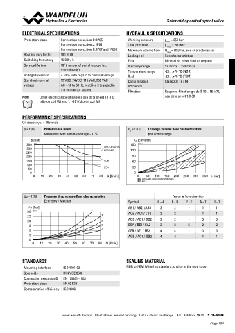
             p = f (Q)  Performance limits                        Q  = f (Q)  Leakage volume flow characteristics
                                                                   L
                       Measured with nominal voltage -10 %                  per control edge
                 p [bar]                                             Q [cm /min]
                                                                          3
              350  K1010                                           150  K0232_3
              300                                     AB1/AB3/ACB/  120
                                                      AFB/AGB
              250
              200                                                   90
              150                                     ADB           60
              100
               50                                     BEA           30
                0                                                    0
                  0   10  20  30  40   50  60  70  80  Q [l/min]       0   50  100  150  200  250  300  350 p [bar]
                                                                         AB3/AB1/ACB/ADB/AFB/AGB
                                                                         BEA


             Δp = f (Q)  Pressure drop volume flow characteristics                       Volume flow direction
                       Economy / Medium                           Symbol         P - A  P - B  P - T  A - T  B - T
               ∆p [bar]                                           AB1 / AB2  /AB3  2     2      -      1      1
               30  K0171                       5                  ACB / AC1 / CB2  2     2      -      1      1
               25                                   1
               20                                   2             ADB / AD1 / DB2  2     2      -      3      3
               15                                   3             BEA / BE1 / EA2  2     2      5      2      2
               10                                   4             AFB / AF1 / FB2  4     4      -      3      3
                5                                                 AGB / AG1 / GB2  4     4      -      1      1
                0
                 0   10  20   30  40  50  60   70  80  Q [l/min]


            STANDARDS                                            SEALING MATERIAL
             Mounting interface  ISO 4401-03                     NBR or FKM (Viton) as standard, choice in the type code
             Solenoids           DIN VDE 0580
             Connection execution D  EN 175301 – 803
             Protection class    EN 60 529
             Contamination efficiency  ISO 4406


                                www.wandfluh.com  Illustrations are not binding  Data subject to change  3/4  Edition: 19 49  1.2-59 E
                                                                                                            Page 155
   150   151   152   153   154   155   156   157   158   159   160