Page 160 - Softbound_Edition_19_en
P. 160

Solenoid operated spool valve
                                                                                Solenoid operated spool valve                                                                                                              WDMFA06-../L8


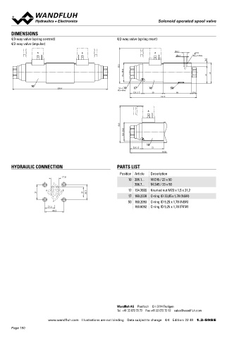
       DIMENSIONS                                                                                                                  Solenoid operated spool valve
       4/3-way valve (spring centred)                      4/2-way valve (spring reset)                                            Flange construction                                  NG6
       4/2-way valve (impulse)                                                                                                        4/3-way with spring centred mid position          ISO 4401-03
                                                                                                                                    ◆
                    A                     B                                   A            9.5                                      ◆  4/2-way with spring reset
                                                                                           5.2   M D= 5.2Nm                         ◆  Q  = 80 l/min
                                                                                                                                       max
                                                                                                         8                          ◆  p  = 350 bar
                                                                                                                                       max
                                                             85.5
                                                               45
                                                                                                           49
                                                                W =                                      41
                 10
                               230.4                          12    17     10         50
                                                            M D=9Nm                                                                DESCRIPTION                                          APPLICATION
                                                                     31.2     50          68      12.6
                                                                                                                                   Direct operated solenoid spool valve with 4 connections in 5 cham-  Spool valves are mainly used for controlling direction of movement
                                                                                  161.8
                                                                                                                                   ber design. With the solenoids deenergised, the spool is held in the   and stopping of hydraulic cylinders and motors. The direction of
                                                                                                                                   center position by the spring (4/3), or switched back to the offset   movement is determined by the position of the spool and its symbol.
                                                                           A                                                       position (4/2). Precise spool fit, low leakage, long service life time.    Switching performance limits and leakage of the valves must be
                                                                                                                                   Spool made from hardened steel, body from high quality hydraulic   taken into account when designing the system. Solenoid operated

                                                                                                                                   cast steel. Wide range of standard and special voltages.        spool valves are suitable for machine tools and handling systems of
                                                              88.3                                                                                                                      any kind.


                                                               45
                                                                M =
                                                                          10
                                                                     28.2    53
                                                                                  161.8                                            SYMBOL

                                                                                                                                                                      AB1                    AB2
                                                                                                                                                                        A B               A B
       HYDRAULIC CONNECTION                                PARTS LIST                                                                                               a    b                a     b
                                                             Position Article  Description                                                                     a               b      a                b
                                 17.8                                                                                                                                   P T               P T
                                                                 10 206.1...  W.E45 / 23 x 50
                            T                                       206.7...  M.S45 / 23 x 50                                                ACB                      AC1                    CB2
                                                                                                                                             A B                        A B               A B
                        A       B                                12 154.2605  Knurled nut M23 x 1,5 x 31,2
                    31                     21    32.5                                                                                    a    o    b                a    b                  a   b
                                                                 17 160.2330  O-ring ID 33,05 x 1,78 (NBR)                          a                    b     a               b      a                b
                            P                                    50 160.2093  O-ring ID 9,25 x 1,78 (NBR)                                    P T                        P T               P T
                          21.5                                      160.6092  O-ring ID 9,25 x 1,78 (FKM)                                    ADB                      AD1                    DB2
                            40.5                                                                                                             A B                        A B               A B
                                                                                                                                              o                           b                 a
                                                                                                                                         a         b                a                           b
                                                                                                                                    a                    b    a                b      a                b
                                                                                                                                             P T                        P T               P T


                                                                                                                                             BEA                      BE1                    EA2
                                                                                                                                             A B                        A B               A B
                                                                                                                                          a   o     b                a    b                 a     b
                                                                                                                                    a                    b     a                b     a                b
                                                                                                                                             P T                        P T               P T


                                                                                                                                             AFB                      AF1                    FB2
                                                                                                                                             A B                        A B               A B
                                                                                                                                              o                           b                 a
                                                                                                                                         a         b                a                           b
                                                                                                                                    a                    b     a                b     a                b
                                                                                                                                             P T                        P T               P T

                                                                                                                                             AGB                      AG1                    GB2
                                                                                                                                             A B                        A B               A B
                                                                                                                                              o                           b                 a
                                                                                                                                         a         b                a                           b
                                                                                                                                    a                    b     a                b     a                b
                                                                                                                                             P T                        P T               P T

                                                           Wandfluh AG  Postfach  CH-3714 Frutigen
                                                           Tel. +41 33 672 72 72  Fax +41 33 672 72 12  sales@wandfluh.com

                         www.wandfluh.com  Illustrations are not binding  Data subject to change  4/4  Edition: 22 48  1.2-59S E                       www.wandfluh.com  Illustrations are not binding  Data subject to change  1/4  Edition: 16 27  1.2-60 E
       Page 160
   155   156   157   158   159   160   161   162   163   164   165