
Page 156 - Softbound_Edition_19_en
P. 156
Solenoid operated spool valve
Solenoid operated spool valve Solenoid operated spool valve
DIMENSIONS Solenoid operated spool valve stainless
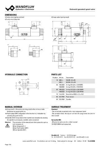
4/3-way valve (spring centred) 4/2-way valve (spring reset) Flange construction NG6
4/2-way valve (impulse) ISO 4401-03
◆ 4/2-way impulse execution, detented
9.5 ◆ 4/3-way with spring centred mid position
A B A
5.5 MD= 5.2Nm ◆ 4/2-way with spring reset
◆ Q = 50 l/min
max
83 8 ◆ p = 350 bar
max
45 49
W = 41
DESCRIPTION APPLICATION
10 Direct operated solenoid spool valve with 4 connections in 5 cham- Spool valves are mainly used for controlling direction of movement
208 70 60 10 50
MD= 5Nm ber design. With the solenoids deenergised, the spool is held in the and stopping of hydraulic cylinders and motors. The direction of
20 51 68 13
center position by the spring (4/3), or switched back to the offset movement is determined by the position of the spool and its symbol.
152
HF1 HS1 position (4/2). With the impulse spool (4/2), the spool is held in the The stainless execution is especially suitable for the use in wet and
51 57 switching position by the detent. salty environment.
37 37 A
80 90
86
45 SYMBOL
M =
AB3 AB1 AB2
A B A B A B
10 a b a b a b
a b a b a
17 53 b
152 P T P T P T
ACB AC1 CB2
A B A B A B
HYDRAULIC CONNECTION PARTS LIST a o b a b a b
Position Article Description a P T b a P T b a P T b
17.8
10 206.1... W.E45 / 23 x 50 ADB DB2
T AD1
206.7... M.S45 / 23 x 50 A B A B A B
A B 50 160.2093 O-ring ID 9,25 x 1,78 (NBR) a o b a b a b
31 21 32.5 160.6092 O-ring ID 9,25 x 1,78 (FKM) a b a b a b
P T P T P T
P 60 160.2222 O-ring ID 22,22 x 2,62 (NBR)
BEA
21.5 160.6222 O-ring ID 22,22 x 2,62 (FKM) A B BE1 A B A B EA2
40.5 70 154.2701 Knurled nut M23 x 1,5 x 19,7
a o b a b a b
80 253.7004 Push-button a b a b a b
90 253.7002 Spindle P T P T P T
GENERAL SPECIFICATIONS ACTUATION
MANUAL OVERRIDE SURFACE TREATMENT
◆ Integrated (–) Actuation pin integrated in the armature tube. Standard: Designation 4/2-, 4/3-spool valve Actuation Switching solenoid, wet pin push type,
Actuation by pressing the pin -The valve body is painted with a two component paint Construction Direct operated pressure tight
◆ Push-button (HF1) Integrated in the knurled nut. Actuation by -The armature tube, the slip-on coil and the plug screw are zinc-ni- Mounting Flange construction Execution W.E45 / 23 x 50 (Data sheet 1.1-182)
pressing the push-button ckel coated Nominal size NG6 according to ISO 4401-03 M.S45 / 23 x 50 (Data sheet 1.1-181)
◆ Spindle (HS1) Integrated in the knurled nut. Actuation by turning Actuation Switching solenoid Connection Connector socket EN 175301 – 803
the spindle (continuously variable valve actuation) Optionally (K8): Ambient temperature -25…+70 °C Connector socket AMP Junior-Timer
Attention! The actuation of the manual override is possible up to a -All external parts are zinc-nickel coated if > +50 °C, then no undervoltage is Connector Deutsch DT04 – 2P
tank pressure of: ISO 9227 (800 h) salt spray test admissible
40 bar Integrated (–) Weight 1,53 kg (1 solenoid Economy)
40 bar Push-button (HF1)
100 bar Spindle (HS1) 2,07 kg (2 solenoids Economy)
MTTFd 150 years
Wandfluh AG Postfach CH-3714 Frutigen
Tel. +41 33 672 72 72 Fax +41 33 672 72 12 sales@wandfluh.com
www.wandfluh.com Illustrations are not binding Data subject to change 4/4 Edition: 19 49 1.2-59 E www.wandfluh.com Illustrations are not binding Data subject to change 1/4 Edition: 22 48 1.2-59S E
Page 156