
Page 150 - Softbound_Edition_19_en
P. 150
Solenoid operated spool valve
Solenoid operated spool valve Solenoid operated spool valve
PERFORMANCE SPECIFICATIONS DIMENSIONS
Oil viscosity u = 30 mm /s 4/3-way valve (spring centred) 4/2-way valve (spring reset)
2
4/2-way valve (impulse)
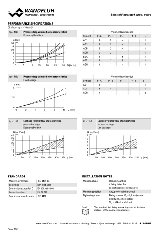
Δp = f (Q) Pressure drop volume flow characteristics Volume flow direction
Economy / Medium Symbol P - A P - B P - T A - T B - T A B A 9.5
p [bar] AB1 2 2 - 1 1 5.2 MD= 5.2Nm
30 K1029 4 2 AB3 2 2 - 1 1 6
25 1 80.5
20 ACB 2 2 - 1 1 37 46
15 3 ADB 2 2 - 1 1 V = 40
10 BEA 1 1 4 1 1
5 AFB 1 1 3 1 1 10 173.6 Economy 70 60 10 50
0 193.6 Medium MD=5Nm
0 5 10 15 20 25 30 Q [l/min] AGB 1 1 - 1 1 40 Economy
18.2 50 Medium 57.2 8.1
HF1 HS1 123.5 Economy
43 44 133.5 Medium
30 30
Δp = f (Q) Pressure drop volume flow characteristics Volume flow direction 80 90 A
Low Leakage Symbol P - A P - B P - T A - T B - T
p [bar] AB1 1 1 - 1 1
5 K1122_neu 1 AB3 1 1 - 1 1 80.3 35
ADB 1 1 - 2 2 N =
2
2.5
10
15.2 53
0 133.5
0 2 4 6 8 10 Q [l/min]
HYDRAULIC CONNECTION MANUAL OVERRIDE
◆ Integrated (–) Actuation pin integrated in the armature tube.
Q = f (Q) Leakage volume flow characteristics Q = f (Q) Leakage volume flow characteristics Actuation by pressing the pin
L
L
per control edge per control edge 17.8 Push-button (HF1) Integrated in the knurled nut. Actuation by
Economy/Medium Low Leakage T ◆
pressing the push-button
Q [cm /min] Q [cm /min] A B ◆ Spindle (HS1) Integrated in the knurled nut. Actuation by turning
3
3
40 K1031 12 K1032 31 21 32.5 the spindle (continuously variable valve actuation)
35 10
30 P Attention! The actuation of the manual override is possible up to a
25 8 21.5 tank pressure of:
20 6 40.5 40 bar Integrated (–)
15 4
10 40 bar Push-button (HF1)
5 2 100 bar Spindle (HS1)
0 0
0 50 100 150 200 250 300 350 p [bar] 0 50 100 150 200 250 300 350 p [bar]
PARTS LIST ACCESSORIES
Position Article Description Mating connector grey (A) Article no. 219.2001
10 206.2... V.E37 / 19 x 40 Mating connector black (B) Article no. 219.2002
V.E37 / 19 x 50 Mounting screws Data sheet 1.0-60
260.5... N.S35 / 19 x 50
STANDARDS INSTALLATION NOTES Threaded subplates Data sheet 2.9-30
50 160.2093 O-ring ID 9,25 x 1,78 (NBR)
Mounting interface ISO 4401-03 Mounting type Flange mounting 160.6092 O-ring ID 9,25 x 1,78 (FKM) Multi-station subplates Data sheet 2.9-60
Solenoids DIN VDE 0580 4 fixing holes for 60 160.2187 O-ring ID 18,72 x 2,62 (NBR) Horizontal mounting blocks Data sheet 2.9-100
Connection execution D EN 175301 – 803 socket head screws M5 x 45 160.6187 O-ring ID 18,72 x 2,62 (FKM) Technical explanations Data sheet 1.0-100
Protection class EN 60 529 Mounting position Any, preferably horizontal 70 154.2700 Knurled nut Filtration Data sheet 1.0-50
Contamination efficiency ISO 4406 Tightening torque Fixing screws M = 5,2 Nm (screw Relative duty factor Data sheet 1.1-430
D
quality 8.8, zinc coated) 80 253.7001 Push-button
M = 5 Nm knurled nut 90 253.7000 Spindle
D
Note! The length of the fixing screw depends on the base
material of the connection element.
Wandfluh AG Postfach CH-3714 Frutigen
Tel. +41 33 672 72 72 Fax +41 33 672 72 12 sales@wandfluh.com
www.wandfluh.com Illustrations are not binding Data subject to change 4/5 Edition: 21 28 1.2-58 E www.wandfluh.com Illustrations are not binding Data subject to change 5/5 Edition: 21 28 1.2-58 E
Page 150