Page 159 - Softbound_Edition_19_en
P. 159

Solenoid operated spool valve
                                                                                     Solenoid operated spool valve


            PERFORMANCE SPECIFICATIONS
            Oil viscosity u = 30 mm /s
                             2
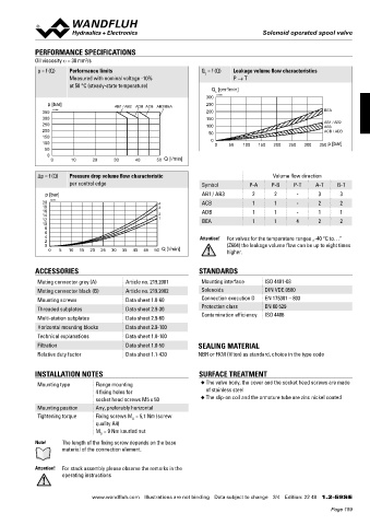
             p = f (Q)  Performance limits                        Q  = f (Q)  Leakage volume flow characteristics
                                                                   L
                       Measured with nominal voltage -10%                   P → T
                       at 50 °C (steady-state temperature)           Q  [cm /min]
                                                                          3
                                                                      L
                                                                   300  K4199
                p [bar]               AB1 / AB2  ADB ACB AB3/BEA   250
               350  K4196                                          200                                   BEA
               300                                                 150
               250                                                 100                                   AB1 / AB2
                                                                                                         AB3
               200                                                  50                                   ACB / ADB
               150
               100                                                   0  0  50  100  150  200  250  300  350  p [bar]
               50
                0
                 0      10     20     30     40    50  Q [l/min]

             Δp = f (Q)  Pressure drop volume flow characteristic                        Volume flow direction
                       per control edge                           Symbol         P-A    P-B     P-T    A-T    B-T
                p [bar]                                           AB1 / AB3       2      2      -      3      3
               20  K4291                            4             ACB             1      1      -      2      2
               18                                   3
               16                                                 ADB             1      1      -      1      1
               14                                   2
               12                                   1             BEA             1      1      4      2      2
               10
               8
               6
               4                                                 Attention!  For valves for the temperature ranges „-40 °C to…”
               2
               0                                                          (Z604) the leakage volume flow can be up to eight times
                 0  5  10  15  20  25  30  35  40  45  50  Q [l/min]      higher.

            ACCESSORIES                                          STANDARDS

             Mating connector grey (A)   Article no. 219.2001     Mounting interface  ISO 4401-03
             Mating connector black (B)  Article no. 219.2002     Solenoids           DIN VDE 0580
             Mounting screws             Data sheet 1.0-60        Connection execution D  EN 175301 – 803
                                                                  Protection class    EN 60 529
             Threaded subplates          Data sheet 2.9-30
             Multi-station subplates     Data sheet 2.9-60        Contamination efficiency  ISO 4406
             Horizontal mounting blocks  Data sheet 2.9-100
             Technical explanations      Data sheet 1.0-100
             Filtration                  Data sheet 1.0-50       SEALING MATERIAL
             Relative duty factor        Data sheet 1.1-430      NBR or FKM (Viton) as standard, choice in the type code


            INSTALLATION NOTES                                   SURFACE TREATMENT
             Mounting type      Flange mounting                   ◆  The valve body, the cover and the socket head screws are made
                                4 fixing holes for                 of stainless steel
                                socket head screws M5 x 50        ◆  The slip-on coil and the armature tube are zinc nickel coated
             Mounting position  Any, preferably horizontal
             Tightening torque  Fixing screws M  = 5,1 Nm (screw
                                            D
                                quality A4)
                                M  = 9 Nm knurled nut
                                 D
            Note!    The length of the fixing screw depends on the base
                     material of the connection element.


            Attention!  For stack assembly please observe the remarks in the
                     operating instructions


                               www.wandfluh.com  Illustrations are not binding  Data subject to change  3/4  Edition: 22 48  1.2-59S E
                                                                                                            Page 159
   154   155   156   157   158   159   160   161   162   163   164