Page 154 - Softbound_Edition_19_en
P. 154

Solenoid operated spool valve
                                                                                Solenoid operated spool valve                                                                                                Solenoid operated spool valve


       TYPE CODE                                                                                                                   ELECTRICAL SPECIFICATIONS                            HYDRAULIC SPECIFICATIONS
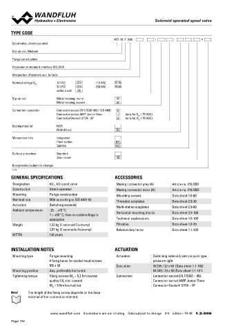
                                                           WD  M  F  A06  -     -     /        -           #                        Protection class   Connection execution D: IP65      Working pressure   p  = 350 bar
                                                                                                                                                                                                             max
       Spool valve, direct operated                                                                                                                    Connection execution J: IP66      Tank pressure      p   = 200 bar
                                                                                                                                                                                                             Tmax
                                                                                                                                                       Connection execution G: IP67 and IP69K  Maximum volume flow  Q  = 80 l/min, see characteristics
       Slip-on coil, Medium                                                                                                                                                                                  max
                                                                                                                                    Relative duty factor  100 % DF                       Leakage oil        See characteristics
       Flange construction                                                                                                          Switching frequency  15'000 / h                      Fluid              Mineral oil, other fluid on request
                                                                                                                                    Service life time  10  (number of switching cycles,   Viscosity range   12 mm /s…320 mm /s
                                                                                                                                                        7
                                                                                                                                                                                                                2
                                                                                                                                                                                                                         2
       International standard interface ISO, NG6
                                                                                                                                                       theoretically)                    Temperature range   -25…+70 °C (NBR)
       Designation of symbols acc. to table                                                                                         Voltage tolerance  ± 10 % with regard to nominal voltage  fluid         -20…+70 °C (FKM)
                                                                                                                                    Standard nominal   12 VDC, 24VDC, 115 VAC, 230 VAC   Contamination      Class 20 / 18 / 14
       Nominal voltage U      12 VDC    G12       115 VAC   R115                                                                    voltage            AC = 50 to 60 Hz, rectifier integrated in
                   N
                              24 VDC    G24       230 VAC   R230                                                                                                                         efficiency
                              without coil   X5                                                                                                        the connector socket              Filtration         Required filtration grade ß 10…16 ≥ 75,
                                                                                                                                   Note!    Other electrical specifications see data sheet 1.1-182          see data sheet 1.0-50
       Slip-on coil           Metal housing, round          W
                              Metal housing, square         M                                                                               (slip-on coil W) and 1.1-181 (slip-on coil M)
       Connection execution   Connector socket EN 175301-803 / ISO 4400   D
                              Connector socket AMP Junior-Timer   J   (only for U  ≤ 75 VDC)
                                                                       N
                              Connector Deutsch DT04 - 2P    G   (only for U  ≤ 75 VDC)                                            PERFORMANCE SPECIFICATIONS
                                                                       N
                                                                                                                                   Oil viscosity u = 30 mm /s
                                                                                                                                                    2
       Sealing material       NBR                                                                                                   p = f (Q)                                            Q  = f (Q)
                              FKM (Viton)                   D1                                                                                Performance limits                          L        Leakage volume flow characteristics
                                                                                                                                              Measured with nominal voltage -10 %                  per control edge
       Manual override        Integrated                                                                                                p [bar]                                             Q [cm /min]
                                                                                                                                                                                                 3
                              Push-button                   HF1                                                                      350  K1010                                           150  K0232_3
                              Spindle                       HS1                                                                                                              AB1/AB3/ACB/
                                                                                                                                     300                                     AFB/AGB      120
       Surface protection     Standard                                                                                               250                                                   90
                              Zinc-nickel                   K8                                                                       200
                                                                                                                                     150                                     ADB           60
       Design index (subject to change)                                                                                              100                                     BEA           30
       1.2-59                                                                                                                         50
                                                                                                                                       0                                                    0
                                                                                                                                                                                                           150
                                                                                                                                                                                                      100
                                                                                                                                                                                                  50
       GENERAL SPECIFICATIONS                              ACCESSORIES                                                                   0   10  20  30  40   50  60  70  80  Q [l/min]       0  AB3/AB1/ACB/ADB/AFB/AGB 200  250  300  350 p [bar]
                                                                                                                                                                                                BEA
       Designation        4/2-, 4/3-spool valve             Mating connector grey (A)    Article no. 219.2001
       Construction       Direct operated                   Mating connector black (B)   Article no. 219.2002
       Mounting           Flange construction               Mounting screws              Data sheet 1.0-60                          Δp = f (Q)  Pressure drop volume flow characteristics                       Volume flow direction
       Nominal size       NG6 according to ISO 4401-03      Threaded subplates           Data sheet 2.9-30                                    Economy / Medium                           Symbol         P - A  P - B  P - T  A - T  B - T
       Actuation          Switching solenoid                Multi-station subplates      Data sheet 2.9-60                            ∆p [bar]                                           AB1 / AB2  /AB3  2     2       -      1      1
       Ambient temperature  -25…+70 °C                      Horizontal mounting blocks   Data sheet 2.9-100                           30  K0171                       5                  ACB / AC1 / CB2  2     2       -      1      1
                          if > +50 °C, then no undervoltage is                                                                        25                                   1
                          admissible                        Technical explanations       Data sheet 1.0-100                           20                                   2             ADB / AD1 / DB2  2     2       -      3      3
       Weight             1,53 kg (1 solenoid Economy)      Filtration                   Data sheet 1.0-50                            15                                   3             BEA / BE1 / EA2  2     2      5       2      2
                          2,07 kg (2 solenoids Economy)     Relative duty factor         Data sheet 1.1-430                           10                                   4             AFB / AF1 / FB2  4     4       -      3      3
       MTTFd              150 years                                                                                                    5                                                 AGB / AG1 / GB2  4     4       -      1      1
                                                                                                                                       0
                                                                                                                                        0   10  20   30  40  50  60   70  80  Q [l/min]
       INSTALLATION NOTES                                  ACTUATION

       Mounting type      Flange mounting                   Actuation          Switching solenoid, wet pin push type,
                          4 fixing holes for socket head screws                pressure tight                                      STANDARDS                                            SEALING MATERIAL
                          M5 x 50                           Execution          W.E45 / 23 x 50  (Data sheet 1.1-182)                Mounting interface  ISO 4401-03                     NBR or FKM (Viton) as standard, choice in the type code
       Mounting position  Any, preferably horizontal                           M.S45 / 23 x 50 (Data sheet 1.1-181)                 Solenoids           DIN VDE 0580
       Tightening torque  Fixing screws M  = 5,2 Nm (screw   Connection        Connector socket EN 175301 – 803                     Connection execution D  EN 175301 – 803
                                      D
                          quality 8.8, zinc coated)                            Connector socket AMP Junior-Timer                    Protection class    EN 60 529
                          M  = 5 Nm knurled nut                                Connector Deutsch DT04 – 2P
                            D                                                                                                       Contamination efficiency  ISO 4406
       Note!   The length of the fixing screw depends on the base
               material of the connection element.


                           www.wandfluh.com  Illustrations are not binding  Data subject to change  2/4  Edition: 19 49  1.2-59 E                      www.wandfluh.com  Illustrations are not binding  Data subject to change  3/4  Edition: 19 49  1.2-59 E
       Page 154
   149   150   151   152   153   154   155   156   157   158   159