Page 164 - Softbound_Edition_19_en
P. 164

WDMFA06-../L8
                                                                                Solenoid operated spool valve                                                                                                Solenoid operated spool valve


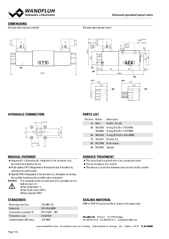
       DIMENSIONS                                                                                                                  Solenoid operated spool valve with inductive
       4/3-way valve (spring centred)                      4/2-way valve (spring reset)                                            switching position monitoring                        NG6
                                                                                                                                                                                        ISO 4401-03
                                                                                                                                   Flange construction
                                                                                                                                    ◆  4/2-way impulse execution, dentented
                                                                                                   4                                ◆  4/3-way with spring centered mid position
               A                               B                M D  = 7 Nm  A                    M D  = 5.2 Nm                     ◆  4/2-way with spring reset
                                                                                         Ø 9.5
                                                                                         Ø 5.5                                      ◆  Q  = 80 l/min
                                                                                                                                       max
                                                                                                       (8)                          ◆  p  = 350 bar
                                                               85.8                                                                     max
                                                                  45                                    41  49
                                                                                         A P B                                     DESCRIPTION
                                                                                                                                   Spool valve according to data sheet 1.2-59 with additional inductive
               10                                                70
                                                                      (16.7)   53          68          12.6                        switching  position  monitoring.  The  contactless  sensor  transmits
                                                                  60                                                               the spool position to a step signal.


                              207.4                                                 150.3
                                                                                               50
                                                                 HF1                   HS1
                                                                      50.7                  57.2
                                                                       37.2                   37.2
                                                                                80                     90                          TYPE CODE
                                                                                                                                                                                                       WD  M  F  A06  -                #
                                                                                                                                    Spool valve, direct operated
                                                                                                                                    Slip-on coil Medium

                                                                                                                                    Flange construction

       HYDRAULIC CONNECTION                                PARTS LIST                                                               International standard interface ISO NG6
                                                             Position Article  Description                                          Other type designation according to type code data sheet 1.2-59
                                 17.8
                                                                 10 206.7...  M.S45 / 23 x 50
                            T                                                                                                       Polarity /Signal output /Monitoring
                                                                 50 160.2093  O-ring ID 9.25 x 1.78 (NBR)                           PNP / NO / Single                    Z603
                        A       B                                   160.6092  O-ring ID 9.25 x 1.78 (FKM)                           PNP / NC / Single                     Z482
                    31                     21    32.5                                                                               NPN / NO / Single                     Z680
                                                                 60 160.2222  O-ring ID 22.22 x 2.62 (NBR)                          PNP / NO / Double*                   Z72 / Z603
                            P                                    70 154.2701  Knurled nut                                           PNP / NC / Double*                   Z72 / Z482
                          21.5                                   80 253.7004  Push-button                                           NPN / NO / Double*                   Z72 / Z680
                            40.5                                                                                                    *not in combination with 4/3-way (spring centred)
                                                                 90 253.7002  Spindle
                                                                                                                                    Design index (subject to change)
                                                                                                                                    1.2-62
       MANUAL OVERRIDE                                     SURFACE TREATMENT
       ◆  Integrated (–) Actuation pin integrated in the armature tube.   ◆  The valve body is painted with a two component paint
         Actuation by pressing the pin                      ◆  The screw plug is zinc coated
       ◆  Push-button (HF1) Integrated in the knurled nut. Actuation by   ◆  The slip-on coil and the armature tube are zinc-nickel coated
         pressing the push-button
       ◆  Spindle (HS1) Integrated in the knurled nut. Actuation by turning
         the spindle (continuously variable valve actuation)
       Attention!  The actuation of the manual override is possible up to a
               tank pressure of:
               40 bar Integrated (–)
               40 bar Push-button (HF1)
               100 bar Spindle (HS1)

       STANDARDS                                           SEALING MATERIAL
       Mounting interface     ISO 4401-03                  NBR or FKM (Viton) as standard, choice in the type code
       Solenoids              DIN VDE 0580
       Connection execution D  EN 175301 – 803
       Protection class       EN 60 529                    Wandfluh AG  Postfach  CH-3714 Frutigen
       Contamination efficiency  ISO 4406                  Tel. 033 672 72 72  Fax 033 672 72 12  sales@wandfluh.com

                           www.wandfluh.com  Illustrations are not binding  Data subject to change  4/4  Edition: 16 27  1.2-60 E                      www.wandfluh.com  Illustrations are not binding  Data subject to change  1/3  Edition: 19 33  1.2-62 E
       Page 164
   159   160   161   162   163   164   165   166   167   168   169