
Page 1045 - Softbound_Edition_19_en
P. 1045
Proportional
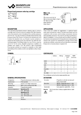
Proportional pressure reducing valve
pressure reduced valves Proportional pressure reducing valve
DIMENSIONS Proportional pressure reducing cartridge
With analog interface M22x1,5 Cavity drawing acc. to ◆ pilot operated M22 x 1,5
Amplifier and controller ISO 7789–22–04–0–98 ◆ Q = 60 l/min ISO 7789
max
40 21, 22 25, 30
◆ p = 400 bar x II 2 G Ex db IIC T6, T4
max
◆ p = 350 bar
N red max x II 2 D Ex tb III C T80 °C, T130 °C
X2
x I M2 Ex db I Mb
X1 (3) Class I Division 1
Class I Zone 1
83 X4 (Nur Regler) 50 80 90 (2)
15 (controller only) 60 70
DESCRIPTION APPLICATION
Pilot operated proportional pressure reducing valve in screw-in These valves are suitable for applications in explosion-hazard
A(1) (1)
35 cartridge construction for cavity according to ISO 7789. Proportio- areas, open cast and also in mines. The electrical remote control in
17.5 nally to the solenoid current, the solenoid force and the pressure in conjunction with process controls allows economical solutions
s30 M22x1.5 T(3) P(2) (1) port A (1) rise. The valve functions practically independently of the with repeatable processes. The screw-in cartridge is perfectly sui-
17 18 pressure in port P (2). Pressure increase in the consumer port A (1) table for installation in control blocks and is installed in sandwich-
20 95 For detailed cavity drawing
135 60 and cavity tools see data sheet 2.13-1004 to above the adjusted value, e.g. through an active consumer, is (vertical stacked systems) and in flange plates (corresponding data
195 avoided by discharging excess oil to the tank T (3). With the sole- sheets in this register). For machining the cartridge cavity in steel
noid deenergised, the oil flows freely from port P (2) to consumer and aluminum blocks, cavity tools are available (hire or purchase).
With fieldbus interface With fieldbus interface
Amplifier Controller port A (1). For the control, Wandfluh proportional amplifiers are Please refer to the data sheets in register 2.13.
available (see register 1.13). The pressure tight encapsulated
Ex-protection solenoid coil prevents an explosion on the inside
X2 X2
penetrating to the outside as well as an ignitable surface tempe-
X1 X1
rature.
83 X3 X3 SYMBOL CERTIFICATES
101
X4 Surface Mining Standard M248
(A) 1 -25 °C Electronic
35 A(1) to…
17.5 ATEX x x x x
s30 M22x1.5 T(3) P(2) 17.5 IECEx x x x x
90 60 (P) 2 (T) 3 CCC x x x x
150
EAC x x x x
Australia x x x
PARTS LIST ACCESSORIES
Flange-/sandwich plate NG4-Mini Data sheet 2.3-820 MA x x x
Position Article Description Flange-/sandwich plate NG6 Data sheet 2.3-840 UL / CSA x x
15 253.8000 HB 4,5 Manual override (data sheet 1.1-300) Flange-/sandwich plate NG10 Data sheet 2.3-860
Data sheet 2.9-210
Line mount body
17 160.2187 O-ring ID 18,72 x 2,62 (NBR) • Set-up software see start-up The certificates can be found on www.wandfluh.com
18 160.2170 O-ring ID 17,17 x 1,78 (NBR) • Cable to adjust the settings through interface USB GENERAL SPECIFICATIONS ACTUATION
A(1)
20 154.2700 Knurled nut (from plug type A to Mini B, 3 m) article no. 219.2896 Designation Proportional pressure reducing valve Actuation Proportional solenoid, wet pin push
21 223.1317 Dummy plug M16 x1,5 • Cable connector for analog interface: Construction Pilot operated type, pressure tight
22 160.6131 O-ring ID 13,00 x1,5 – straight, soldering contact article no. 219.2330 Mounting Screw-in cartridge construction Execution MKY45 / 18x60 (data sheet 1.1-183)
25 062.0102 Cover square – 90°, soldering contact article no. 219.2331 Nominal size M22 x 1,5 according to ISO 7789 MKU45 / 18x60 (data sheet 1.1-184)
30 072.0021 Gasket 33,2 x 59,9 x 2 Recommended cable size: Actuation Proportional solenoid Connection Cable gland for cable Ø 6,5…14 mm
– Outer diameter 9…10,5 mm
P(2)
40 208.0100 Socket head cap screw M4 x10 – Single wire max. 1 mm 2
T(3)
50 160.2188 O-ring ID 18,77 x 1,78 (NBR) – Recommended wire size: Ambient temperature Operation as T6 Attention! The UL execution is always supplied without cable
2
160.6188 O-ring ID 18,77 x 1,78 (FKM) 0…25 m = 0,75 mm (AWG18) -25…+40 °C (L9) gland
2
60 160.2156 O-ring ID 15,60 x 1,78 (NBR) 25…50 m = 1 mm (AWG17) Operation as T4
160.6156 O-ring ID 15,60 x 1,78 (FKM) -25…+90 °C (L9)
70 160.2140 O-ring ID 14,00 x 1,78 (NBR) -25…+70 °C (L15 / L17)
160.6141 O-ring ID 14,00 x 1,78 (FKM) Technical explanation see data sheet 1.0-100 Weight 2,2 kg
80 049.3196 Backup ring RD 16,1 x 19 x 1,4 MTTFd 150 years
90 049.3176 Backup ring RD 14,1 x 17 x 1,4
Wandfluh AG Tel. +41 33 672 72 72 E-mail: sales@wandfluh.com Illustrations not obligatory Data sheet no.
Postfach Fax +41 33 672 72 12 Internet: www.wandfluh.com Data subject to change 2.3-632E 4/4 www.wandfluh.com Illustrations are not binding Data subject to change 1/4 Edition: 21 21 2.3-635 E
CH-3714 Frutigen Edition 17 01
Page 1045