
Page 1042 - Softbound_Edition_19_en
P. 1042
21, 22
40
X2
83
X4 (Nur Regler)
(controller only)
15
A(1)
35
17.5
T(3)
P(2)
s30
17
18
20
135
X1
X3
83
X3
X4
17.5
T(3)
90 X1 35 X2 95 195 s30 M22x1.5 25, 30 60 M22x1.5 P(2) 50 60 60 A(1) 80 70 90 101 17.5 X1 X2
150
Proportional Proportional-
pressure reduced valves
Proportional pressure reducing valve pressure reduced valves
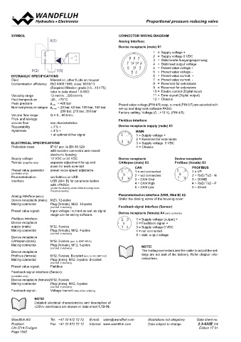
SYMBOL CONNECTOR WIRING DIAGRAM INBETRIEBNAHME
A(1) Analog interface: For DSV amplifiers as a rule no parameter settings by the customer Additional information can be found on our website:
are required. The plugs have to be connected in accordance with the «www.wandfluh.com»
Device receptacle (male) X1 chapter «Pin assignment».
1 = Supply voltage + Controllers will be supplied configurated as amplifiers. Switching into Free-of-charge download of the «PASO»-software and the instruction
8 9 1 2 = Supply voltage 0 VDC controller mode and setting of the adjustments of the controller must manual for the «DSV» hydraulic valves as well as the operation instruc-
tion CANopen protocol eg. Profibus DP protocol with device profile
3 = Stabilisierte Ausgangsspannung
7 12 10 2 4 = Stabilised output voltage be done by the customer using the set-up software (USB interface, Mini B). DSP-408 for «DSV».
8 9 1 6 11 3 4 = Preset value voltage +
8 9
1
P(2) T(3) 7 12 10 2 5 4 5 = Preset value voltage -
7 12 10 2
HYDRAULIC SPECIFICATIONS 6 11 3 6 = Preset value current +
11 3
6
Fluid Mineral oil, other fluids on request 5 4 7 = Preset value current - /s
4
5
Contamination efficiency ISO 4406:1999, class 18/16/13 8 = Reserved for extensions CHARACTERISTICS Oil viscosity ν = 30 mm 2
(Required filtration grade β 6…10 ≥ 75) 9 = Reserved for extensions p = f (Q) Pressure volume flow characteristics p = f (Q) Pressure volume flow characteristics
red
red
refer to data sheet 1.0-50/2 2 3 10 = Enable control (Digital input) (Maximal adjustable pressure) (Minimal adjustable pressure)
Viscosity range 12 mm /s…320 mm /s 1 5 4 11 = Error signal (Digital output) ٭ Consumption resistance dependent on system
2
2
Fluid temperature -20…+70 °C 2 3 12 = Chassis 2 3 p [bar] p [bar] a: P N red = 160/200/275/350 bar b: P N red = 20/63/100 bar
Peak pressure p max = 400 bar 5 Preset value voltage (PIN 4/5) resp. current (PIN 6/7) are selected with 400 K0434_1 40 K0443_2 a
1
8 9
5
1
4
Nominal pressure ranges p N red = 20 bar, 63 bar, 100 bar, 160 bar, set-up and diagnosis software PASO. 1 4 P N red = 350 bar
7 12 10 2
200 bar, 275 bar, 350 bar Factory setting: Voltage (0…+10 V), (PIN 4/5) 300 P N red = 275 bar 30 b
Volume flow range Q = 0…60 l/min 6 11 3 200 P N red = 200 bar 20
4
5
Pilot- and leakage Fieldbus interface:
volume flow see characteristics 100 P N red = 100 bar 10 ∗
1
2
2
1
Repeatability ≤ 2 % ∗ Device receptacle supply (male) X1 P N red = 63 bar
Hysteresis ≤ 4 % ∗ 3 5 4 MAIN 0 P N red = 20 bar 0
4
3
∗ at optimal dither signal 2 1 2 2 3 1 1 = Supply voltage + 60 40 20 0 20 40 60 60 40 20 0 20 40 60
5 5 2 = Reserved for extensions 2 1 2 1 A T Q [l/min] P A A T Q [l/min] P A
ELECTRICAL SPECIFICATIONS 3 4 3 1 4 4 3 = Supply voltage 0 VDC 3 5 4 3 4
Protection class IP 67 acc. to EN 60 529 4 = Chassis p = f (l) Pressure adjustment characteristics Q st + L = f (p) Pilot- and leakage volume flow characteristic [A (1) → T (3)]
red
with suitable connector and closed [at Q = 0 l/min]/(s corresponds to preset value signal) (Pressure in P (2) = 350 bar)
electronic housing Inlet pressure: p +10 %
N
Supply voltage 12 VDC or 24 VDC Device receptacle Device receptacle Mesured with closed port A
2
3
Ramps (amplifier only) separate adjustment for up and CANopen (male) X3 Profibus (female) X3 p [bar] Q [cm /min]
3
5
down for each solenoid 2 3 1 4 CAN PROFIBUS 120 K0764_3 1000 K0760_1
Preset value generator preset value speed adjustable 5 2 1 1 = not connected 2 3 1 = VP P N = 100 bar
2
1
(controller only) 1 4 5 2 = not connected 5 2 = RxD / TxD - N 90 800
Parameterisation via fieldbus or USB 3 4 3 = CAN Gnd 4 1 4 600
3
Interface USB (Mini B) for parameterisation 3 = DGND 60 P N = 63 bar
with «PASO» 4 = CAN High 4 = RxD / TxD - P 400
(under the closing screw of the housing cover, 8 9 1 5 = CAN Low 5 = Shield 30
Preset ex-works) 7 12 10 2 P N = 20 bar 200
Analog interface (MAIN): Parameterisation interface (USB, Mini B) X2 0 0
6
11 3
50
100
Device receptacle (male) M23, 12-poles Under the closing screw of the housing cover 0 10 20 30 40 50 60 70 80 90 100 s [%] 0 P N red = 20/63/100 bar 150 200 250 300 350 p [bar]
4
5
Mating connector Plug (female), M23, 12-poles 2 3 P N red = 160/200/275/350 bar
(not incl. in delivery) Feedback signal interface (Sensor) p = f (l) Pressure adjustment characteristics
red
5
Preset value signal: Input voltage / current as well as signal 1 4 [at Q = 0 l/min]/(s corresponds to preset value signal)
range can be set by software. Device receptacle (female) X4 (only controller) Inlet pressure: p N +10 %
Fieldbus interface: 2 3 1 = Supply voltage (output) + Mesured with closed port A
Device receptacle 5 2 = Feedback signal + p [bar]
supply (male) M12, 4-poles 1 4 3 = Supply voltage 0 VDC 400 K0764_2
Mating connector Plug (female), M12, 4-poles 4 = not connected P N red = 350 bar
(not incl. in delivery) 5 = stab. output voltage 300
Device receptacle P N red = 275 bar
CANopen (male) M12, 5-poles (acc. to DRP 303-1) 200 P N red = 200 bar
Mating connector Plug (female), M12, 5-poles NOTE! P N red = 160 bar
(not incl. in delivery) 100
Device receptacle The mating connectors and the cable to adjust the set-
2
1
Profibus (female) M12, 5-poles, B-coded (acc. to IEC 947-5-2) 2 1 tings are not part of the delivery. Refer chapter «Ac- 0
Mating connector Plug (male), M12, 5-poles, B-coded 5 cessories». 0 10 20 30 40 50 60 70 80 90 100 s [%]
(not incl. in delivery) 3 4 3 4 Factory settings:
Preset value signal: Fieldbus
Dither set for optimal hysteresis
Feedback signal interface (Sensor): = Deadband: Solenoid switched off
(controller only) with command preset value signal < 5 %
Device receptacle (female) M12, 5-poles = Regulated pressure in port A (1) at 70 % of preset value signal::
Mating connector Plug (male), M12, 5-poles 250 bar with pressure range 350 bar
(not incl. in delivery) 2 3 192 bar with pressure range 275 bar
Feedback signal:: Voltage / current state when ordering 5 143 bar with pressure range 200 bar
1 4 112 bar with pressure range 160 bar
NOTE! 72 bar with pressure range 100 bar
Detailed electrical characteristics and description of 45 bar with pressure range 63 bar
«DSV» electronics are shown on data sheet 1.13-76. 14,5 bar with pressure range 20 bar
Wandfluh AG Tel. +41 33 672 72 72 E-mail: sales@wandfluh.com Illustrations not obligatory Data sheet no. Wandfluh AG Tel. +41 33 672 72 72 E-mail: sales@wandfluh.com Illustrations not obligatory Data sheet no.
Postfach Fax +41 33 672 72 12 Internet: www.wandfluh.com Data subject to change 2.3-632E 2/4 Postfach Fax +41 33 672 72 12 Internet: www.wandfluh.com Data subject to change 2.3-632E 3/4
CH-3714 Frutigen Edition 17 01 CH-3714 Frutigen Edition 17 01
Page 1042