
Page 1040 - Softbound_Edition_19_en
P. 1040
Proportional-
Proportional pressure reducing valve
Proportional pressure reducing valve pressure reduced valves
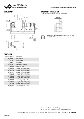
DIMENSIONS HYDRAULIC CONNECTION Proportional pressure reducing valve
Cavity drawing according to ISO 7789–22–04–0–98 Screw-in cartridge M22x1,5
• Integrated amplifier or controller electronics ISO 7789
s30 M22x1.5 • Pilot operated
15 M22x1.5 • Q max = 60 l/min
= 400 bar
• p
76.8 MD=5.5Nm (3) (2) (3) • p max = 350 bar
37.1 (1) N red max
W = (2) DESCRIPTION FUNCTION APPLICATION
Pilot operated proportional pressure reducing
Proportional pressure reducing valves with
The proportional pressure reducing valve con-
12 17 10 18 50 60 70 80 90 (1) valve with integrated electronics as a screw-in trols the pressure in port A (1). Proportionally integrated electronics are well suited for de-
cartridge. Thread M22x1,5 for cavity according
to the solenoid current solenoid force and pres-
manding applications, in which the pressure
MD=5Nm
78.4 59.9 to ISO 7789. These plug & play valves are fac- sure in port A rise. The valve functions practi- frequently has to be changed. They are imple-
(1)
144.5 tory set and adjusted. High valve-to-valve re- cally independently of the pressure in port mented in systems calling for good valve-to-
producibility. Housing for electronics with pro-
P (2). The control connection is provided by an
valve reproducibility, easy installation, comfort-
HB0 Note! For detailed cavity drawing and cavity tools see data tection class IP67 for harsh environment. Se- analog interface or a fieldbus interface (CANo- able operation and high precision in industrial
sheet 2.13-1004 ven standard pressure levels are available. pen, J1939 or Profibus DP). Parameter setting hydraulics as well as in mobile hydraulics. The
15 Adjustment by a Wandfluh proportional sole- and diagnosis with the free-of-charge software integrated controller reliefs the machine con-
MD= 9.5Nm noid (VDE standard 0580). The cartridge and «PASO» or via fieldbus interface. The USB pa- trol system and operates the pressure regula-
74.8 the solenoid made of steel are zinc coated and rameterisation interface is accessible through tion in a closed control loop. The proportional
therefore rustprotected. The housing for the
a cover flap.. «PASO» is a Windows program
pressure reducing cartridge is very suitable for
35 elctronics is made of aluminium. in the flow diagram style, which enables the mounting in control blocks, flange bodies and
Optionally these valves are available with in- intuitive setting and storing of all variable pa- sandwich plates of the size NG4-Mini, NG6 and
M = tegrated controller. As feedback value genera- rameters. The data remain saved in case of NG10. (Please note the separate data sheets
tor sensors with voltage or current output can a power failure and can also be reproduced in register 2.3). Cavity tools are available for
10 be directly connected. The available controller and transferred to other DSVs. machining the cavities in steel and aluminium
structures are optimised for the utilisation with (hire or purchase). Please refer to the data
hydraulic drives. sheets in register 2.13.
PARTS LIST
Position Article Description
10 206.2… W.S37 / 19 x 50 TYPE CODE
260.5… M.S35 / 19 x 50 M V P PM22 - - / M E - HB4,5 #
12 154.2700 Knurled nut Pressure reducing valve
15 253.8000 HB4,5 manual override Pilot operated
239.2033 HB0 Screw plug Proportional
17 160.2187 O-ring ID 18,72 x 2,62 (NBR) Screw-in thread M22x1,5
18 160.2170 O-ring ID 17,17 x 1,78 (NBR)
Nominal pressure range p N red 20 bar 20 200 bar 200
50 160.2188 O-ring ID 18,77 x 1,78 (NBR) 63 bar 63 275 bar 275
160.6188 O-ring ID 18,77 x 1,78 (FKM) 100 bar 100 350 bar 350
60 160.2156 O-ring ID 15,60 x 1,78 (NBR) 160 bar 160
160.6156 O-ring ID 15,60 x 1,78 (FKM) Nominal voltage U N 12 VDC G12
G24
24 VDC
70 049.3196 Backup ring rd 16,1 x 19 x 1,4 Slip-on coil Metal housing, square
80 160.2140 O-ring ID 14,00 x 1,78 (NBR) Execution connection Integrated electronics
160.6141 O-ring ID 14,00 x 1,78 (FKM)
Hardware configuration
90 049.3176 Backup ring rd 14,1 x 17 x 1,4 With analog signal (0…+10 V factory set) A1
With CANopen acc. to DSP-408 C1
With Profibus DP in accordance with Fluid Power Technology P1
With CAN J1939 (on request) J1
Function
Amplifier
Controller with current feedback signal (0...20 mA / 4...20 mA) R1
Controller with voltage feedback signal (0...10 V) R2
Sealing material NBR
FKM (Vitron) D1
Manual override
Änderungs-Index (wird vom Werk eingesetzt)
Wandfluh AG Postfach CH-3714 Frutigen
Tel. +41 33 672 72 72 Fax +41 33 672 72 12 sales@wandfluh.com
Wandfluh AG Tel. +41 33 672 72 72 E-mail: sales@wandfluh.com Illustrations not obligatory Data sheet no.
www.wandfluh.com Illustrations are not binding Data subject to change 4/4 Edition: 17 47 2.3-629 E Postfach Fax +41 33 672 72 12 Internet: www.wandfluh.com Data subject to change 2.3-632E 1/4
CH-3714 Frutigen Edition 17 01
Page 1040