
Page 896 - Softbound_Edition_19_en
P. 896
Pressure reducing valve
Pressure reducing valve Pressure reducing valve
GENERAL SPECIFICATIONS HYDRAULIC SPECIFICATIONS DIMENSIONS
Designation Pressure reducing valve Working pressure p = 400 bar Key adjustment „S” Control knob adjustment „D”
max
Construction Pilot operated Nominal pressure p N red = 63 bar, 160 bar, 350 bar 25.5
Mounting Screw-in cartridge construction range 17 s4
Nominal size M18 x 1,5 according to Wandfluh Volume flow range Q = 0…25 l/min
standard Leakage oil See characteristics 30 20
Actuation Manually Fluid Mineral oil, other fluid on request 40
Ambient temperature -25…+90 °C Viscosity range 12 mm /s…320 mm /s s13
2
2
Weight 0,11 kg key adjustment Temperature range -25…+90 °C (NBR)
0,12 kg control knob adjustment fluid -20…+90 °C (FKM) 52.1
0,15 kg cover Contamination Class 18 / 16 / 13 44.6 s19
MTTFd 150 years efficiency
Filtration Required filtration grade ß 10…16 ≥ 75,
see data sheet 1.0-50 Ø23 96.1
PERFORMANCE SPECIFICATIONS 88.6
Oil viscosity u = 30 mm /s M18x1.5 50
2
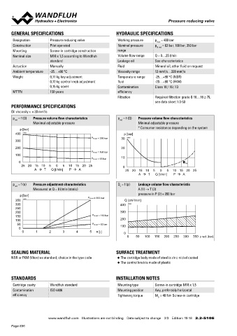
p = f (Q) Pressure volume flow characteristics p = f (Q) Pressure volume flow characteristics
red red HYDRAULIC CONNECTION
Maximal adjustable pressure Minimal adjustable pressure 3 (T) 60
* Consumer resistance depending on the system 44 Cavity drawing according to Wandfluh standard
p [bar] 70
400 K0465 p [bar]
P N red = 350 bar 30 K0463 2 (P) M18x1.5
300
200 20 1 (A) 80
P N red = 160 bar 90 (3)
100
P N red = 63 bar 10 (2)
0 ∗ Cover „A”
25 20 15 10 5 0 5 10 15 20 25 0
A T Q [l/min] P A 25 20 15 10 5 0 5 10 15 20 25 23 (1)
A T Q [l/min] P A (1)
p = f (n) Pressure adjustment characteristics Q = f (p) Leakage volume flow characteristic 25
red L Note! For detailed cavity drawing and cavity tools see data
Measured at Q = 0 l/min (static) A (1) → T (3) sheet 2.13-1020
p [bar] pressure in P (2) = 350 bar
P N red = 350 bar
350 K0323 Q [cm /min]
3
300 400 K0464
250 50.1 PARTS LIST
200 300
150 P N red = 160 bar Position Article Description
100 200 20 114.2224 Control knob
50 P N red = 63 bar 100
0 94.1 25 032.0611 Cover rd 23 / 3 x 35
0 1 2 3 4 5 n [-] 0 30 193.1061 Retainer rd 6 DIN 6799
0 50 100 150 200 250 300 350 p red. [bar] 40 153.1402 Hexagon nut 0,5d M8 x 1
ACCESSORIES 50 160.2156 O-ring ID 15,60 x 1,78 (NBR)
Adjustment types for screw-in cartridges Data sheet 2.0-50 160.6156 O-ring ID 15,60 x 1,78 (FKM)
SEALING MATERIAL SURFACE TREATMENT Flange body / sandwich plate NG3-Mini Data sheet 2.2-600 60 160.2111 O-ring ID 11,11 x 1,78 (NBR)
NBR or FKM (Viton) as standard, choice in the type code ◆ The cartridge body made of steel is zinc-nickel coated Threaded body Data sheet 2.9-210 160.6111 O-ring ID 11,11 x 1,78 (FKM)
◆ The control knob is made of plastic
Technical explanations Data sheet 1.0-100 70 049.3156 Backup ring rd 12,1 x 15 x 1,4
Filtration Data sheet 1.0-50 80 160.2093 O-ring ID 9,25 x 1,78 (NBR)
STANDARDS INSTALLATION NOTES 160.6092 O-ring ID 9,25 x 1,78 (FKM)
90 049.3137 Backup ring rd 10,6 x 13,5 x 1,4
Cartridge cavity Wandfluh standard Mounting type Screw-in cartridge M18 x 1,5
Contamination ISO 4406 Mounting position Any, preferably horizontal
efficiency Tightening torque M = 40 Nm Screw-in cartridge
D
Wandfluh AG Postfach CH-3714 Frutigen
Tel. +41 33 672 72 72 Fax +41 33 672 72 12 sales@wandfluh.com
www.wandfluh.com Illustrations are not binding Data subject to change 2/3 Edition: 19 18 2.2-510 E www.wandfluh.com Illustrations are not binding Data subject to change 3/3 Edition: 19 18 2.2-510 E
Page 896