
Page 895 - Softbound_Edition_19_en
P. 895
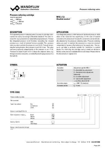
Pressure reducing valve
Pressure reducing valves Pressure reducing valve
Pressure reducing cartridge
CHARACTERISTICS oil viscosity υ = 30 mm /s ◆ pilot operated M18 x 1,5
2
p = f (Q) Pressure volume flow characteristics p = f (n) Pressure adjustment characteristics p = 400 bar Wandfluh standard
red
red
(Maximal adjustable pressure) [at Q = 0 l/min (static)] ◆ max
∗ Consumer resistance dependent on system ◆ p N red max = 350 bar
p [bar] p [bar] ◆ Q = 25 l/min
max
P N red = 50 bar
60 K1175 50 K1174
50 40
40 P N red = 50 bar 30 P N red = 32 bar
30 DESCRIPTION APPLICATION
26 20 P N red = 32 bar 20 P N red = 18 bar Pilot operated pressure reducing valve in screw-in cartridge cons- The integrated pressure relief makes an additional pressure relief
∗
10 P N red = 18 bar 10 truction for cavity according to Wandfluh standard. The valve re- valve in the consumer line superfluous. In the case of several
0 0 duces the input pressure to an adjustable output pressure. Through consumers, the pressure of the specific consumers can be individu-
6 4 20 2 72.9 0 2 4 6 0 1 2 3 4 5 6 n [-] the integrated pressure relief function, exceeding the reduced ally adjusted by the pressure reducing valve. Pressure reducing
A T Q [l/min] P A pressure as a result of external forces is avoided. The pressure valves are used to maintain the pressure in a consumer constant
DIMENSIONS/SECTIONAL DRAWINGS reducing valve controls the pressure in port A (1). Through increa- independent of pressure fluctuations on the supply side. The scr-
sing the spring tension, the pressure in port A(1) rises. The valve ew-in cartridge is perfectly suitable for installation in control
Key adjustment „S“ Cavity drawing acc. to operates practically independently of the pressure in port P (2). blocks. For machining the cartridge cavity in steel and aluminum
Wandfluh standard
30 40 s30 Pressure increase in port A (1) to above the adjusted value, e.g. blocks, cavity tools are available (hire or purchase). Please refer to
s24
s13 M16 M16x1.5 through an active consumer, is avoided by discharging excess oil to the data sheets in register 2.13.
(3) (2) the tank (3).
Ø 17 (1)
s4
(3)
50 60 65 SYMBOL ACTUATION
65.4 27.1
(2) Actuation Adjustment spindle M8 x 1
92.5 (A) 1 Execution S = blockable key adjustment
(1) D = blockable knob adjustment
Turning knob adjustment „D“ Optionally:
(1)
K = lockable adjustment
For detailed cavity drawing (P) 2 (T) 3 G = star handle adjustment
A (1) see data sheet 2.13-1051 → see Data sheet 2.0-50
Actuation angle a = 1800 ° (5 rotations)
b
26 Actuation stroke S = 5 mm
b
P (2) T (3)
20 72.9 TYPE CODE
M V PM18 - - #
Pressure reducing valve
PARTS LIST Pilot operated
40
Position 30 Article Description s30
s24 Type of adjustment Key S
20 114.2224 Knob M16 Control knob D
s13
30 193.1061 Safety plate RD6 DIN 6799 (3) (2) Cover A
40 Ø 17 153.1402 Hexagonal nut 0,5D M8x1 (1) Screw-in cartridge M18 x 1,5
50 s4 160.2140 O-ring ID 14,00 x 1,78 (NBR)
160.8140 O-ring ID 14,00 x 1,78 (FKM) Nominal pressure range p 63 bar 63
60 160.2093 O-ring ID 9,25 x 1,78 (NBR) 50 60 65 N 160 bar 160
160.8092 O-ring ID 9,25 x 1,78 (FKM) 27.1 350 bar 350
65.4
65 160.2076 O-ring ID 7,65 x 1,78 (NBR)
92.5
160.8076 O-ring ID 7,65 x 1,78 (FKM) Technical explanation see data sheet 1.0-100E Sealing material NBR
FKM (Viton) D1
Design index (subject to change)
2.2-510
A (1)
Wandfluh AG Tel. +41 33 672 72 72 E-mail: sales@wandfluh.com Illustrations not obligatory Data sheet no.
Postfach Fax +41 33 672 72 12 Internet: www.wandfluh.com Data subject to change 2.2-508E 2/2 www.wandfluh.com Illustrations are not binding Data subject to change 1/3 Edition: 19 18 2.2-510 E
CH-3714 Frutigen P (2) T (3) Edition 16 18
Page 895