Page 893 - Softbound_Edition_19_en
P. 893

Pressure reducing valve
                                                                                          Pressure reducing valves

            Pressure reducing valve
            Screw-in cartridge                            M16x1,5
            •  Direct operated
            •  Q max    =  26  6 l/min                 Wandfluh standard
            •  p  max    =  210 bar (350 bar)
            •  p     =  50 bar
               N red max            20  72.9
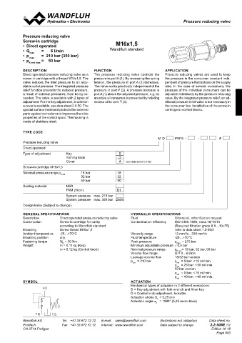
            DESCRIPTION                        FUNCTION                           APPLICATION
            Direct operated pressure reducing valve as a   The pressure reducing valve controls the   Pressure reducing valves are used to keep
            screw-in cartridge with a thread M16x1,5. The   pressure in port A (1). By increasing the spring   the pressure in the consumer constant inde-
            valve reduces the inlet pressure to an adju-  tension, the pressure in port A (1) increases.   pendent of pressure fluctuations on the supply
            stable outlet pressure. The integrated pressure   The valve works practically independent of the   side. In the case of several consumers, the
                                                     s30
                           30
                               40
            relief function prevents the reduced pressure,   s24  pressure in port P (2). A pressure increase in   pressure of the individual consumers can be
                                                          M16
            a result of external pressures, from being ex-  port A (1) above the adjusted pressure, e.g. by   adjusted individually by the pressure reducing
                                   s13
            ceeded. The valve is available with 2 types of   an active oil consumer, is prevented by reliefing   valve. By the integrated pressure relief, an ad-
                                                             (3)
                                                                 (2)
            adjustment. For the key adjustment, in addition   excess oil to tank T (3).  ditional pressure relief valve is not necessary in
                       Ø 17
            a cover is available, see data sheet 2.0-50. The        (1)           the consumer line. Installaltion of the screw-in
                           s4
            special surface treatment protects the external                       cartridge in control blocks.
            parts against corrosion and improves the slide
            properties of the control spool. The housing is   50 60 65
            made of stainless steel.     65.4               27.1
                                               92.5
            TYPE CODE
                                                                               M  D     PM16  -      -         #
            Pressure reducing valve
            Direct operated
            Type of adjustment    Key                       S                 A (1)
                                  Turning knob             D
                                  Cover                     A   (see data sheet 2.0-50)
            Screw-in cartridge M16x1,5
            Nominal pressure range p N red     18 bar      18
                                         32 bar            32
                                         50 bar            50             P (2)   T (3)
 26
            Sealing material      NBR
                                  FKM (Viton)              D1
                                  System pressure  max. 210 bar
 20  72.9                         System pressure  max. 350 bar  Z406
            Design-Index (Subject to change)

            GENERAL SPECIFICATIONS                               HYDRAULIC SPECIFICATIONS
            Description       Direct operated pressure reducing valve  Fluid           Mineral oil, other fluid on request
 30  40  s30  Construction    Screw-in cartridge for cavity      Contamination efficiency   ISO 4406: 1999, class 18/16/13
 s24                          according to Wandfluh standard                           (Required filtration grade ß 6…10≥75)
 s13  M16   Mounting          Screw thread M16x1,5                                     refer to data sheet 1.0-50/2
     (3)  (2)  Ambient temperature   -25…+70°C                   Viscosity range       12 mm /s…320 mm /s
                                                                                            2
                                                                                                     2
             (1)
 Ø 17       Mounting position   any                              Fluid temperature     -25…+70 °C
                                                                                            = 210 bar
                                                                 Peak pressure
                                                                                       p
            Fastening torque
                              M  = 30 Nm
 s4                             D                                                       max
            Weight:           m = 0,11 kg (Key)                  Minimum adjustable pressure  < 0,5 bar
                              m = 0,12 kg (Control knob)         Nominal pressure range   p N red = 18 bar, 32 bar, 50 bar
  50 60 65                                                       Volume flow range     Q = 0…6 l/min
 65.4  27.1                                                      Leakage volume flow   18/32 bar version
                                                                 p   = 210 bar         p   = 0 bar: < 10 ml / min.
 92.5                                                             sys                   red
                                                                                       p   = 25 bar: < 50 ml / min.
                                                                                        red
                                                                                       50 bar version
                                                                                       p   = 0 bar: < 10 ml / min.
                                                                                        red
                                                                                       p   = 40 bar: < 40 ml / min.
                                                                                        red
            SYMBOL                                               ACTUATION
                                                                 Mechanical types of actuation in 2 different executions:
                      A (1)                                      S = Key adjustment with fork wrench and Allen key
                                                                 D = Control knob adjustment, lockable
                                                                 Actuation stroke S  = 5,25 mm
                                                                              b
                                                                 Actuation angle α   = 1890° (5,25 revolutions)
                                                                              b
                   P (2)   T (3)
            Wandfluh AG         Tel.  +41 33 672 72 72   E-mail:  sales@wandfluh.com   Illustrations not obligatory   Data sheet no.
            Postfach            Fax  +41 33 672 72 12   Internet:  www.wandfluh.com   Data subject to change   2.2-508E 1/2
            CH-3714 Frutigen                                                                             Edition 16 18
                                                                                                            Page 893
   888   889   890   891   892   893   894   895   896   897   898