
Page 114 - Softbound_Edition_19_en
P. 114
Solenoids
Solenoid accessory Solenoids
PD2-AMPLIFIER WITH ANALOGUE INTERFACE
Command value scaling F X1-1 Signal recording F X1-1 F X1-2 Amplifier with CANopen interface
Versorgungs-
braun
brown
Supply
The command value can be applied as a voltage, current, digital, fre- Furthermore, the „PD2“ amplifier electronics have a signal recording Tension X1-5
spannung
X1-5
X1-5
grau
gray
voltage
d'alimentation
quency or PWM signal. The scaling takes place via the parameter “In- function. This, by means of PASO, enables the recording of various ELECTRICAL SPECIFICATIONS
F = Sicherung träge
F = Fuse slow
terface”. Furthermore, the command value can be monitored for a cable system signals, such as command value, solenoid current, etc., which F = Sécurité inerte IP 67 acc. to EN 60 529 Dither Frequency adjustable 4…500 Hz
Protection class
break. A dead band can also be set. can be represented on a common time axis. Supply voltage 8…32 V Factory setting 80 Hz
Residual ripple < +/-5 % Level adjustable 0…400 mA
Fixed command value Solenoid driver Fuse low Factory setting 180 mA
There is 1 fixed command value available, which can be selected via A Pulse-Width-Modulated current output is available. A dither signal is No-load current approx. 20 mA Temperature drift <1 % at ∆T = 40 °C
the digital input. This function has to be configurated before in PASO. superimposed, whereby the dither frequency and the dither level are Max. current Digital inputs 1 input high-active, no pull-up/down
USB/PASO
USB/PASO separately adjustable. The minimum (Imin) and maximum (Imax) cur- USB/PASO consumption No-load current + 2,5 A per solenoid Switching threshold high 6...32 VDC
Ramp generator rent can be adjusted. The solenoid output can also be configurated as Switching threshold low 0…1 VDC
Two linear ramps for up and down are available which can be adjusted switching solenoid output. In this case, a power reduction can be ad- Solenoid current: Usable as frequency input
0...1 VDC
0...1 VDC
0...1 VDC
separately. X1-3 weiss justed. X1-3 white X1-3 blanc • Minimal current I Adjustable 0…I mA (frequency 5...5000 Hz) and as PWM
6...32 VDC 6...32 VDC 6...32 VDC min max
Versorgungs- F X1-1 braun Supply F X1-1 brown Tension F X1-2 Factory setting 30 mA input (automatic frequency recognition)
Valve type spannung X1-5 grau Optimisation of characteristic curve X1-5 gray d'alimentation X1-5 Adjustable I …2450 m A USB interface Via digital input
voltage
min
Adjustment possibilities: switching solenoid or proportional solenoid. An adjustable characteristic curve „Command value input – solenoid • Maximal current I max MP35/19x50-..-12, Factory setting 1360 mA Requires the Wandfluh USB adapter
Adapter
F = Fuse slow
F
F
F
USB/PASO
USB-PD2
Versorgungs- F = Sicherung träge braun current output“ enables an optimised (e.g. linearised) characteristic of Tension F = Sécurité inerte MP35/19x50-..-24, Factory setting 680 mA EMV
X1-2
X1-1
X1-1
brown
Supply
Mode of operation „Command value unipolar/bipolar (1-Sol) the hydraulic system. X1-5 gray d'alimentation X1-5 MP45/23x50-..-12, Factory setting 1490 mA Immunity EN 61 000-6-2
spannung
X1-5
voltage
grau
Dependent on a command value signal (voltage, current, digital, fre- MP45/23x50-..-24, Factory setting 780 mA Emission EN 61 000-6-4
0...1 VDC
F = Sicherung träge
quency or PWM), the solenoid is driven (e.g. 0….10V correspond to Channel enabling F = Fuse slow F = Sécurité inerte MPS60/31x72-..-12, Factory setting 2290 mA
X1-3
weiss
6...32 VDC
0….100 % command value, 0….+100 % command value correspond As per factory setting, the device is enabled („on“). This „enable chan- MPA60/31x72-..-12, Factory setting 2290 mA
to Imin….Imax solenoid driver) nel“ can be set to „on“, „off“ or „external“ (digital input) via PASO or via MPS60/31x72-..-24, Factory setting 1140 mA
USB/PASO menu item. USB/PASO USB/PASO MPA60/31x72-..-24, Factory setting 1140 mA
Hints:
0...1 VDC USB/PASO Digital input: 0...1 VDC USB/PASO 0...1 VDC USB/PASO
if not wired, the state of the digital input is not defined
6...32 VDC X1-3 weiss 6...32 VDC X1-3 white 6...32 VDC X1-3 blanc
Analogue input: if not wired, the voltage input will read 1.11 V constantly.
X1-4
0...1 VDC X1-4 gelb 0...1 VDC yellow X1-4 jaune BLOCK DIAGRAM
0...1 VDC
6...32 VDC X1-2 Adapter X1-3 weiss 6...32 VDC X1-3 white 6...32 VDC X1-3 blanc
X1-2
X1-2
grün
USB/PASO USB-PD2 green vert
X1-5 grau X1-5 grey X1-5 gris brown X1-1
0 % 0...1 VDC 100 % Command value +VCC
Adapter
0 V USB/PASO USB-PD2 X1-3 weiss
10 V
4 mA 6...32 VDC 20 mA Analogue value
0 mA 20 mA
5 Hz 0...1 VDC 5000 Hz X1-3 weiss
- 10 V 6...32 VDC 10 V
grey X1-5
GND
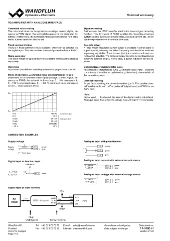
CONNECTION EXAMPLES
X1-4 gelb X1-4 yellow X1-4 jaune Internal Supply PWM Solenoid
Analogue input with potentiometer
Versorgungs- F X1-1 braun Supply voltage F X1-1 brown Tension F X1-2 supply
Supply
X1-2
vert
spannung X1-5 grau voltage 0...10 VDC gray grün X1-2 grün d'alimentation X1-2 green 0...10 VDC X1-2 X1-2 vert
X1-5
X1-2
X1-5 green
0...10 VDC
F
X1-4
X1-2 X1-5
X1-5
Versorgungs- F X1-1 braun Supply F F = Fuse slow +/-10 VDC X1-4 gelb X1-5 grau Tension +/-10 VDC F = Sécurité inerte grey +/-10 VDC X1-4 jaune gris CAN-High yellow X1-4
yellow
X1-1
brown
grau
gris
grey
F = Sicherung träge
X1-5
X1-5
X1-5
spannung X1-5 grau voltage X1-5 gray d'alimentation X1-5
X1-2 grün X1-2 green X1-2 vert
F = Sicherung träge F = Fuse slow F = Sécurité inerte A/D
X1-5 grau X1-5 grey X1-5 gris
green X1-2
Digital input as function input Analogue input current with external current source CAN-Low
USB/PASO USB/PASO USB/PASO
0...20 mA X1-2 grün 0...20 mA X1-2 green 0...20 mA X1-2 vert
4...20 mA X1-5 grau 4...20 mA X1-5 grey 4...20 mA X1-5 gris
USB/PASO USB/PASO USB/PASO
0...1 VDC 0...1 VDC 0...1 VDC
blanc
X1-3
6...32 VDC X1-3 weiss 6...32 VDC X1-3 white 6...32 VDC Analogue input voltage with external voltage source
0...1 VDC 0...1 VDC 0...1 VDC white
blanc
white
X1-2
6...32 VDC X1-3 weiss 6...32 VDC X1-3 0...10 VDC 6...32 VDC grün X1-3 0...10 VDC X1-2 green 0...10 VDC X1-2 vert Digital Input X1-3
X1-5
+/-10 VDC
grey
Adapter CAN-Low +/-10 VDC X1-2 grün X1-5 grau CAN-Low X1-2 green +/-10 VDC CAN-Low X1-5 gris X1-2 vert
USB/PASO USB-PD2
CAN-High
0...10 VDC X1-4
green
0...10 VDC
X1-2
Adapter Digital input as USB interface gelb X1-2 grün CAN-High X1-4 yellow 0...10 VDC CAN-High vert X1-4 jaune
X1-2
USB/PASO USB-PD2 +/-10 VDC X1-5 grau +/-10 VDC X1-5 grey +/-10 VDC X1-5 gris
0...1 VDC VCC
6...32 VDC X1-3 weiss Adapter Push-buttons 7 segment
0...1 VDC brown VCC+ USB-PD2 FLASH display
6...32 VDC X1-3 weiss PC USB USB - Adapter ON DIG white DigInp RAM
TX
0...20 mA
PASO 0...20 mA RX OV grün grey PD2 X1-2 green 0...20 mA X1-2 vert
X1-2
4...20 mA X1-5 grau GND 4...20 mA X1-5 grey 4...20 mA X1-5 gris PASO / USB
0...20 mA X1-2 GND grün 0...20 mA X1-2 green 0...20 mA X1-2 vert
4...20 mA X1-5 grau 4...20 mA X1-5 grey 4...20 mA X1-5 gris
X1-4 gelb X1-4 yellow X1-4 jaune
Plug
X1-2 grün X1-2 green CAN-Low X1-2 grün X1-2 vert CAN-Low X1-2 green CAN-Low X1-2 vert
X1-4 gelb X1-4 yellow USB type B Screw Terminal
jaune
X1-4
X1-4
X1-4
X1-4
gelb
CAN-High
CAN-High
jaune
yellow
X1-2 X1-5
X1-2 X1-5 grau X1-2 X1-5 grey CAN-High Tel. +41 33 672 72 72 vert gris CAN-Low X1-2 green Data sheet no. X1-2 vert Wandfluh AG Tel. +41 33 672 72 72 E-mail: sales@wandfluh.com Illustrations not obligatory Data sheet no.
grün
green
Illustrations not obligatory
E-mail: sales@wandfluh.com
Wandfluh AG
CAN-Low
X1-2
grün
CAN-Low
Internet: www.wandfluh.com
grey
X1-5 grau X1-5 Postfach Fax +41 33 672 72 12 gris Data subject to change 1.1-330E 4/7 Postfach Fax +41 33 672 72 12 Internet: www.wandfluh.com Data subject to change 1.1-330E 5/7
X1-5
CAN-High
CAN-High
CH-3714 Frutigen X1-4 gelb CAN-High X1-4 yellow Edition 21 20 X1-4 jaune CH-3714 Frutigen Edition 21 20
Page 114
0...10 VDC X1-2 grün 0...10 VDC X1-2 green 0...10 VDC X1-2 vert
+/-10 VDC X1-5 grau +/-10 VDC X1-5 grey +/-10 VDC X1-5 gris
0...10 VDC X1-2 grün 0...10 VDC X1-2 green 0...10 VDC X1-2 vert
+/-10 VDC X1-5 grau +/-10 VDC X1-5 grey +/-10 VDC X1-5 gris
0...20 mA X1-2 grün 0...20 mA X1-2 green 0...20 mA X1-2 vert
4...20 mA X1-5 grau 4...20 mA X1-5 grey 4...20 mA X1-5 gris
0...20 mA X1-2 grün 0...20 mA X1-2 green 0...20 mA X1-2 vert
4...20 mA X1-5 grau 4...20 mA X1-5 grey 4...20 mA X1-5 gris
CAN-Low X1-2 grün CAN-Low X1-2 green CAN-Low X1-2 vert
CAN-High X1-4 gelb CAN-High X1-4 yellow CAN-High X1-4 jaune
CAN-Low X1-2 grün CAN-Low X1-2 green CAN-Low X1-2 vert
CAN-High X1-4 gelb CAN-High X1-4 yellow CAN-High X1-4 jaune