
Page 117 - Softbound_Edition_19_en
P. 117
F
F
F
X1-1
Tension
X1-5
X1-5
spannung
X1-5
d'alimentation
gray
voltage
grau
Solenoids Versorgungs- F = Sicherung träge braun Supply F = Fuse slow X1-1 brown USB/PASO F = Sécurité inerte X1-2
Solenoids
USB/PASO Solenoid accessory
USB/PASO
0...1 VDC
DIMENSIONS 2 3 4 5 6 7 8 PD2-AMPLIFIER WITH CANopen INTERFACE X1-3 weiss 0...1 VDC X1-3 white 0...1 VDC X1-3 blanc
1
6...32 VDC 6...32 VDC 6...32 VDC
MP.60/31x72 Command value scaling Signal recording
91.5 MPS45/23x50 MPS35/19x50 The command value can be applied as a CAN-bus, digital, frequency Furthermore, the „PD2“ amplifier electronics have a signal recording
51 Adapter
72.5 or PWM signal. The scaling takes place via the parameter „Interface”. function. This, by means of PASO, enables the recording of various sy-
USB/PASO
A 72.5 A USB-PD2
Furthermore, the command value can be monitored for a cable break. stem signals, such as command value, solenoid current, etc., which
A dead band can also be set. can be represented on a common time axis.
0...1 VDC
28.7 Fixed command value 6...32 VDC X1-3 weiss Solenoid driver
79 64 54
31 38 60 39 23.09 45 32 19.03 35 There is 1 fixed command value available, which can be selected via A Pulse-Width-Modulated current output is available. A dither signal is
the digital input. This function has to be configurated before in PASO. superimposed, whereby the dither frequency and the dither level are
separately adjustable. The minimum (Imin) and maximum (Imax) cur-
50 Ramp generator rent can be adjusted. The solenoid output can also be configurated as
50
B 53 B Two linear ramps for up and down are available which can be adjusted switching solenoid output. In this case, a power reduction can be ad-
70 53
72 19.25 separately. justed.
X1-4 gelb X1-4 yellow X1-4 jaune
Valve type Optimisation of characteristic curve
Adjustment possibilities: switching solenoid or proportional solenoid. An adjustable characteristic curve „Command value input – solenoid vert
X1-2
grün
green
X1-2
X1-2
current output“ enables an optimised (e.g. linearised) characteristic of gris
grey
grau
X1-5
↓
X1-5
↓
X1-5
↓
Mode of operation „Command value unipolar/bipolar (1-Sol)
the hydraulic system.
Valve side Valve side Valve side or PWM), the solenoid is driven (e.g. 0…16383 CAN-command cor- Channel enabling
C C Dependent on a command value signal (CAN-bus, digital, frequency
respond to 0...100 % command value, 0….+100 % command value
correspond to Imin...Imax solenoid driver) As per factory setting, the device can be enabled via CAN-bus. This
„enable channel“ can be set to „bus“, „on“, „off“ or „external“ (digital in-
ANSCHLUSSBELEGUNG put) via PASO or via menu item.
Anschlusskabel
1 brown 1 = + VCC Hint:
2 green 2 = CAN-Low Digital input if not wired, the state of the digital input is not defined
D D
3 white 3 = Dig Inp
4 yellow 4 = CAN-High 0...10 VDC grün 0...10 VDC green 0...10 VDC vert
5 grey 5 = GND +/-10 VDC X1-2 grau +/-10 VDC X1-2 grey +/-10 VDC X1-2 gris
X1-5
X1-5
X1-5
Kanten nach ISO 13715 Oberflächenbeschaffenheit 0 % 100 % Command value
-0.1 Ra 3.2 Winkel m Nennmass >0,5-3 >3-6 >6-30 >30-120
+0.4
START-UP ADDITIONAL INFORMATION -0.3 Allgemein- toleranzen ISO 2768 Längenmasse, Rundungen,Fasen m Auszug Allgemeintoleranzen ISO-2768-1 ±0.3 5 Hz 5000 Hz
H
Geradheit, Ebenheit
Rechtwinkligkeit, Symmetrie
±0.2
±0.1
±0.1
H Längenmasse
Rundlauf,Planlauf
H Radien,
±0.2
Hüllbedingung nach ISO 14405 E
Fasenhöhe
Information regarding installation and commissioning are contained in Material: Wandfluh documentation- ±0.5 ±1 BEH 0 Inc 16383 Inc Bus command value
Gezeichnet
12.11.2014
E 1 brown 01 02.07.2015 BEH Typenbezeichnung richtiggestellt Geprüft 24.11.2015 RP E
the information leaflet supplied with the amplifier electronics and in the Wandfluh electronics general Name Änderungsnr. Änderungsbeschrieb 1.13 Freigegeben M 1:1 24.11.2015 BR
register
Variante MP60 hinzugefügt
17.11.2015
BEH
02
Rev.
Serie freigegeben
Datum
operating instructions. Magnetspule komplett Ersetzt durch: Gewicht 0...20 mA X1-2 grün 0...20 mA X1-2 green 0...20 mA X1-2 vert
0.880 kg
Ersatz für:
Proportional spool valve MP../..x..-P1-..-.. register 1.10 Dok.-Nr. 0164148 Format 4...20 mA X1-5 grau 4...20 mA X1-5 grey 4...20 mA X1-5 gris
A2
Additional information can be found on our website: 2 white Proportional pressure valves Dokument darf ohne schriftliche Einwilligung weder kopiert, Art.-Nr. DB 1.1-330 Revision
register
2.3
02
verwertet noch an Dritte weitergegeben werden.
Zuwiderhandlung ist strafbar und wird gerichtlich verfolgt.
1
5
2.6
«www.wandfluh.com» 2 3 4 Proportional flow control valves register C:\00_Wandfluh\Verkauf\Dokumentation\Reg1.1\0164148 Blatt 1 von 1 CONNECTION EXAMPLES
F F F
CAN connection
Versorgungs- X1-1 braun Supply voltage X1-1 brown Tension X1-2
Supply
Free-of-charge download: spannung X1-5 grau voltage X1-5 gray d'alimentation X1-5
• «PASO-PD2» Parameterisation software ACCESSORIES Versorgungs- F F F
X1-2
X1-1
X1-2
F = Fuse slow
• Operating instruction (*.pdf) USB-adapter PD2 spannung F = Sicherung träge braun Supply CAN-Low X1-1 brown X1-2 grün TensionCAN-Low F = Sécurité inerte green CAN-Low X1-2 vert
Article no. 726.9900
X1-5
X1-5
X1-5
grau
voltage
d'alimentation
gray
incl. USB-cable type A-B, 1,8 m CAN-High X1-4 gelb CAN-High X1-4 yellow CAN-High X1-4 jaune
(for parameterisation via PASO) F = Sicherung träge F = Fuse slow F = Sécurité inerte
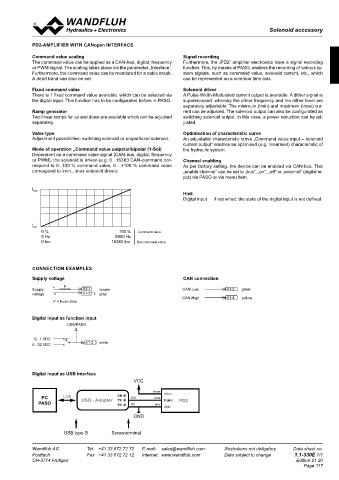
PARAMETER SETTINGS Digital input as function input
The PD2 electronics have push-buttons and a 7 segment display which enable setting the most important parameters. In addition, the digital USB/PASO USB/PASO
USB/PASO
input can be used as a communication interface, through which, by means of the parameterisation software „PASO-PD2“, the complete para-
meterisation and diagnostics can be carried out. For this, the Wandfluh USB-PD2 adapter is required. (not included in the delivery) USB/PASO USB/PASO
USB/PASO
0...1 VDC 0...1 VDC 0...1 VDC
Attention: During the communication, the digital input cannot be used. 6...32 VDC X1-3 weiss 6...32 VDC X1-3 white 6...32 VDC X1-3 blanc
0...1 VDC 0...1 VDC 0...1 VDC
6...32 VDC X1-3 weiss 6...32 VDC X1-3 white 6...32 VDC X1-3 blanc
Adapter
FUNCTION DESCRIPTION USB/PASO USB-PD2
Adapter
USB/PASO USB-PD2 Digital input as USB interface
0...1 VDC
6...32 VDC X1-3 weiss VCC
0...1 VDC
Command Command Solenoid output 6...32 VDC X1-3 weiss brown VCC+
value Fixed Ramp Solenoid PC USB ON DIG white
scaling command generator Valve type USB - Adapter TX DigInp PD2
values driver Current measurement PASO RX OV grey
GND
GND
DigInp DigInp DigInp DigInp
X1-4 gelb X1-4 yellow X1-4 jaune
Error Number Enable Solenoid Enable Error
X1-2
X1-4 X1-2 grün X1-4 X1-2 green USB type B Screwterminal jaune vert
X1-4
gelb
yellow
X1-2 X1-5 grau X1-2 X1-5 grey X1-2 X1-5 gris
vert
green
grün
Wandfluh AG Tel. +41 33 672 72 72 E-mail: sales@wandfluh.com Illustrations not obligatory Data sheet no. Wandfluh AG Tel. +41 33 672 72 72 E-mail: sales@wandfluh.com Illustrations not obligatory Data sheet no.
grey
X1-5
1.1-330E 6/7
Postfach Fax +41 33 672 72 12 Internet: www.wandfluh.com Data subject to change X1-5 grau X1-5 Postfach Fax +41 33 672 72 12 gris Data subject to change 1.1-330E 7/7
Internet: www.wandfluh.com
CH-3714 Frutigen Edition 21 20 CH-3714 Frutigen Edition 21 20
Page 117
0...10 VDC X1-2 grün 0...10 VDC X1-2 green 0...10 VDC X1-2 vert
+/-10 VDC X1-5 grau +/-10 VDC X1-5 grey +/-10 VDC X1-5 gris
0...10 VDC X1-2 grün 0...10 VDC X1-2 green 0...10 VDC X1-2 vert
+/-10 VDC X1-5 grau +/-10 VDC X1-5 grey +/-10 VDC X1-5 gris
0...20 mA X1-2 grün 0...20 mA X1-2 green 0...20 mA X1-2 vert
4...20 mA X1-5 grau 4...20 mA X1-5 grey 4...20 mA X1-5 gris
0...20 mA X1-2 grün 0...20 mA X1-2 green 0...20 mA X1-2 vert
4...20 mA X1-5 grau 4...20 mA X1-5 grey 4...20 mA X1-5 gris
CAN-Low X1-2 grün CAN-Low X1-2 green CAN-Low X1-2 vert
CAN-High
CAN-High
CAN-High
grün
CAN-Low X1-2 X1-4 gelb CAN-Low X1-2 X1-4 yellow CAN-Low X1-2 X1-4 jaune
vert
green
CAN-High X1-4 gelb CAN-High X1-4 yellow CAN-High X1-4 jaune