
Page 109 - Softbound_Edition_19_en
P. 109
Solenoid accessory Solenoid accessories
Solenoid accessory
DIMENSIONS APPLICATION POSSIBILITIES Power reduction plug P04
U I • After switching on, current consumption is reduced to 50 %
On 2 I • Direct mounting on the valve
Action range
• Protection class 67 DIN EN 175301-803
2 • For switching solenoids with DIN plug construction form A ISO 4400
40 I 1
Off
1
1/2
DESCRIPTION FUNCTION APPLICATION
t Power reduction plug for direct mounting on After switching on the supply, the maximum By the IP 67 execution and the wide tempera-
5,5 M3 ca. 380ms the valve. Contact arrangement in accordance current of the solenoid passes for approx. 250 ture range, the power reduction plug is suitable
27 Switching operation at nominal with DIN EN 175301-803, construction form A ms, thereafter the current is limited to half by both for industrial and mobile applications.
The plug can be rotated by 180°. It protects
the cicle controlled output stage. Thereby the
(ISO 4400) for DC switching solenoids. The
62 power, with subsequent power reduction. protection class of the power reduction plug is power consumption of the valve is reduced to continuously energised solenoids (e.g. used
- reduced heating of coil IP 67, mounted according to EN 60529. The below 30 %. as a safety function) from overtemperature
- extended life of solenoid connection cable is injection moulded onto and premature ageing. By overenergisation, a
- shorter disconnection time the plug. valve which is deenergised in normal operation
P03A-1.. 2 1 For optimum design, please contact us. straight through powerfully.
28 3 Switching at elevated nominal power or overvoltage. (eventually seized spool), can be switched
- powerful straight-through switching
- shorter switching time
U: Supply voltage of the power reduction plug CONTENTS TYPE CODE
I: Current consumption of the solenoid P 04 A - 1 D2 #
GENERAL SPECIFICATIONS ................. 1
Plug
START-UP 2 ELECTRICAL SPECIFICATIONS ............ 1 Designation
(This data sheet is enclosed with each power reducing plug) Housing construction form A, contact clearance 18 mm
Examples of connection 12.4 BLOCK DIAGRAM / CONNECTION ........ 1 1 solenoid execution
DC- Version: 28 18 AC- Version: DIMENSIONS ........................................... 2 Supply voltage
F1 S F1 1 S APPLICATION POSSIBILITIES ............... 2 24 VDC
+ 1 1
Supply 2 Supply 2 Design-Index (Subject to change)
GENERAL SPECIFICATIONS HYDRAULIC SPECIFICATIONS
3
3
Plug housing TPU transparent Supply voltage 24 VDC ± 10 %
F1: 12...24VDC (P03A-1D2) = 5A quick break Connection line PUR black 3 x 0,5 mm 2 Suppressor circuit Freewheel diode
90...230VAC/DC (P03A-1B0) = 800mA quick break Length 5 m Status display LED yellow
Weight 130 g Dither Frequency fix 1,1 kHz
Instruction for connection Ambient temperature -25…60 °C Solenoid current I Nmax = 4A (max. switching current)
1 2 3 I Nmax = 2A (max. holding current)
Switching frequency max. 2 Hz
EMC Immunity EN 61000-6-2
Emission EN 61000-4-2
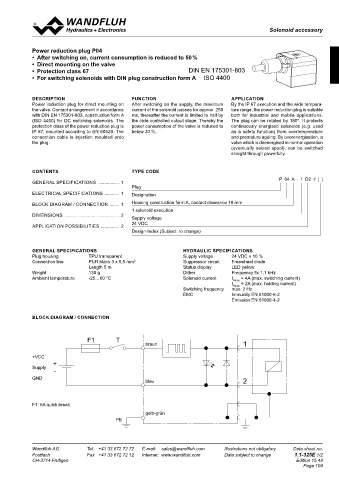
BLOCK DIAGRAM / CONNECTION
ca. 60mm cable Insert cable Connect cable
4 5 6 F1 T
26.5 braun 1
+VCC
+
Supply
-
GND
Pull up the cable Insert the cable again Fasten the plug onto the blau 2
solenoid
Supply voltage
The cable is connected as described above. 3.5
Important warning! M3 F1: 5A quick break
The power supply to the plug version for 90...230VAC/DC must be disconnected or switched of while the cable is being connected to the plug and/ gelb-grün
or while the cover is removed. 28 PE
Installation
To be able to fit the power reduction plug in the 180° reversed position, it is necessoiry to remove the bottom of the plug using a screw driver and
48
to refit it rotated through 180°.
Wandfluh AG Tel. +41 33 672 72 72 E-mail: sales@wandfluh.com Illustrations not obligatory Data sheet no. Wandfluh AG Tel. +41 33 672 72 72 E-mail: sales@wandfluh.com Illustrations not obligatory Data sheet no.
Postfach Fax +41 33 672 72 12 Internet: www.wandfluh.com Data subject to change 1.1-320E 2/2 Postfach Fax +41 33 672 72 12 Internet: www.wandfluh.com Data subject to change 1.1-325E 1/2
CH-3714 Frutigen Edition 03 19 CH-3714 Frutigen Edition 15 48
Page 109