Page 888 - Softbound_Edition_19_en
P. 888

Accumulator unloading valve                                                                                                Accumulator unloading valves
                                                                                  Accumulator loading  valves

                                        2
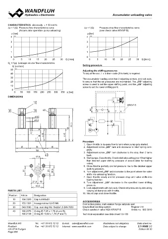
       CHARACTERISTICS  oilviskosity  υ = 30 mm /s                                                                                 Accumulator unloading valve
       ∆p = f (Q)  Pressure-flow characteristics curve       ∆p = f (Q)   Pressure-drop flow characteristics curve                 Sandwich construction
               (Accumulator operation- pump unloading)                 (over check valve ARV6/P-B)                                 •  1-point adjustment                           NG10
         p [bar]                                               p [bar]
         4  K0597                                             4  K0598                                                             •  Pilot operated                            ISO 4401-05
                                                                                                                                   •  Q    =  30 l/min
         3                                                    3                                                                    •  p max   =  400 bar
                                                                                                                                   •  p max    =  350 bar
         2                                                    2                                                                       N max
         1                                                    1                                                                    DESCRIPTION                        FUNCTION                           APPLICATION
                                                                                                                                   Sandwich type pilot operated accumulator un-  If the P pressure exceeds the adjustable un-  Accumulator loading valves are used in hydrau-
         0                                                    0                                                                    loading valve. Mounting interface acc. to ISO   loading point, the pilot spool is opening the   lic systems with accumulators. They allow a low
          0     5    10    15   20    25    30  Q [l/min]       0     5    10    15   20    25    30  Q [l/min]                    4401-05. The valve is available with two types   pilot valve. A control flow starts to flow and the   cost, energy saving system design in cases
       Q  = f (p)  Leakage volume flow-characteristics                                                                             of setting, both interlockable. There are three   back end of the main spool is depressurised.   where the cylinder flow demand varies consi-
        L
              3
          Q [cm /min] B                                     Setting procedure                                                      pressure stages to choose from. The valve has   The resultant pressure difference displaces the   derably or for retaining pressures over a period
                                                                                                                                                                      main spool towards the spring and the valve
                                                                                                                                   an adjustable unloading point and a defined
                                                                                                                                                                                                         of time, e.g. for clamping processes. Note: An
       B 50  K0587                                          Adjusting the shiffing pressures                                       re-switching difference. The steel bodies of   switches to unloading circulation. Because of   additional relief valve for system protection
         40  P        T                                     To adjust the acc ./. v. a drain code (B to tank) is required.         the  sandwich  valve  are  phosphate  coated.   the difference in section in the pilot aerea, the   must be installed. Please refere to the set-up
  P      30  T                                              The accumulator loading valve has 2 adjusting screws, and lock nuts,   Steel cartridge body and adjustment spindle   pilot flow is interrupted as soon as the pressure   and connection exemple on page 2.
                                                                                                                                   galvanised to protect them against corrosion.
                                                                                                                                                                      in the accumulator drops by 15 % or 25 % of
         20  A                                              to ensure that the set pressures are maintained. The „OS“ adjusting    The aluminium knob has a natural anodised   the upper switching point. The pressures at
  A                                                         screw is used to set the upper shifting point, and the „US“ adjusting   finish. The quality of this product is reflected in   the main spool are equilibrated and the spring
         10                                                 screw to set the lower shifting point.                                 the good performance data and design.  displaces the main spool to the closed position.
         0                                                                                                                                                            The pump can now build up the system pres-
           0   50   100  150  200  250  300  350 p [bar]                                                                                                              sure again as far as the unloading point and
                                                                                                                                                                      the cycle starts again.
       DIMENSIONS
                                                                                                    ARV6/P-B
                                                                                           ARV6/P-B                                                                   TYPE CODE
                                                                           42
                                                                  42           P       B    T  A                                                                                                              US     S  A10  -  P     #
                                                                      P       B    T  A
                                                                                                                                                                      Accumulator unloading valve pilot operated
                                                                                                                        ∗ ∗                                           Type of adjustment   screw   S
                                                                                                                                                                                       knob        D
                                                                         M
                                                                M                                                                                                     Sandwich construction
                                                                                                                                                                      International standard interface ISO, NG10

                                                                                                                                                                      Type list / function   in P
                                                            Procedure
                                                             1.  Open throttle to by-pass flow to tank when pump gets started.                                        Pressure range p  100 bar    100
                                                             2.  Adjustment screw „US“: turn anti clockwise to relief spring com-                                                  N   160 bar     160
                                                              pletly.                                                                                                                  350 bar     350
                                                             3.  Adjustment screw „OS“: turn clockwise to the stop, then 2 turns
                                                              back.                                                                                                   Design-Index (Subject to change)
                                                             4.  Start pumpe. Close throttle. Check relief valve setting (min 10 bar higher
                                                              than desired upper shifting pressure of accumulator for loading
                                                              valve).
                                                             5.  Close throttle partially and let pressure rise to the desired upper   GENERAL SPECIFICATIONS                           HYDRAULIC SPECIFICATIONS
                                                              working pressure.                                                    Description      Pilot operated accumulator unloading valve  Fluid        Mineral oil, other fluid on request
                                                             6.  Turn adjustment „OS“ anti clockwise to the point where the valve   Norminal size   NG10 according to ISO 4401-05       Contamination efficiency   ISO 4406:1999, class 18/16/13
                                                              shifts into unloading function.                                      Construction     Sandwich construction                                    (Required filtration grade ß6…10≥75)
                                                             7.  Open throttle slowly and let pressure drop until valve shifts into   Mounting      4 holes for socket cap screw M6                          refer to data sheet 1.0-50/2
                                                              loading function.                                                                     or studs M6                         Viskosity range      12 mm /s…320 mm /s
                                                                                                                                                                                                                  2
                                                                                                                                                                                                                           2
                                                             8.  Turn adjustment „US“ clockwise to the specified lower shifting    Connections      Connection plates                   Fluid temperature    -20…+70 °C
                                                              pressure.                                                                             Multi-station flange subplate       Peak pressure        p max  = 400 bar
                                                             9.  Lock adjustments with lock nuts. Check set pressures by simulating                 Longitudinal stacking system        Norminal pressure    p = 100 bar, p  = 160 bar, p = 350 bar
                                                                                                                                                                                                                        N
                                                                                                                                                                                                                                 N
                                                                                                                                                                                                              N
       PARTS LIST                                             varying oil demands with throttle.                                   Mounting position   any                              Minimum pressure     p  = 50 bar for p  160 / 350 bar
                                                                                                                                                                                                                          N
                                                                                                                                                                                                              min
                                                            10. Mount caps and close throttle.                                     Ambient temperature   -20...+50 °C                                        p  = 25 bar for p  100 bar
                                                                                                                                                                                                              min
                                                                                                                                                                                                                          N
        Position  Article  Designation                                                                                             Fastening torque   M = 9,5 Nm (Qual 8.8)  for fixing screw  Diff. unloading/loading   15 ± 3 % for p  = 160 / 350 bar
                                                                                                                                                      D
                                                                                                                                                                                                                       N
          10    154.7200  Cap nut M6x23                                                                                                             M = 50 Nm for screw cartridge                            25 ± 3 % for p  = 100 bar
                                                                                                                                                                                                                       N
                                                                                                                                                      D
                                                            ACCESSORIES
                                                                                                                                                                                                               min
          20    153.1301  Hexagonal nut 0,8 D M6            Connection plates, multi-station flange subplate and                   Weight           m = 2,7 kg                          Volume flow          Q  =  1…30 l/min

                                                                                                                                                                                                             (over 30 l/min on request)
          30     049.1180  Cop. seal ring NG 18x22x1,5 DIN 7603  longitudinal stacking system   Register 2.9                                                                            Leakage volume flow   Maximum 4 drops/min
                                                            Check sandwich valve NG6 ARV6/P-B   Article no.  662.3010                                                                                        in accumulator operation P - T
          40    160.2076   O-ring ID 7,65 x 1,78 (A and B)
                160.2108  O-ring ID 10,82 x 1,78 (P and T)  Technical explanation see data sheet 1.0-100                                                                                For further hydraulic characteristics refer to data sheet: 2.1-548
       Wandfluh AG        Tel.  +41 33 672 72 72   E-mail:  sales@wandfluh.com   Illustrations not obligatory   Data sheet no.     Wandfluh AG         Tel.  +41 33 672 72 72   E-mail:  sales@wandfluh.com   Illustrations not obligatory   Data sheet no.
       Postfach           Fax  +41 33 672 72 12   Internet:  www.wandfluh.com   Data subject to change   2.1-950E 2/2              Postfach            Fax  +41 33 672 72 12   Internet:  www.wandfluh.com   Data subject to change   2.1-960E 1/2
       CH-3714 Frutigen                                                                            Edition 08 30                   CH-3714 Frutigen                                                                             Edition 03 35
       Page 888
   883   884   885   886   887   888   889   890   891   892   893