
Page 877 - Softbound_Edition_19_en
P. 877
Back pressure valve
Back pressure valve
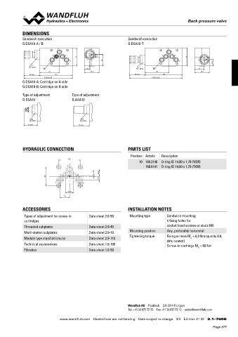
DIMENSIONS
Sandwich execution Sandwich execution
G.DSA10-A / B G.DSA10-T
P P
A B A B
60 60
T To 38 T To
21.5
MD= 60Nm
10 18 MD= 60Nm 10 32
66 49.5 80 49.5
53 max. 110 53 max. 125
163 max. 178 max.
G.DSA10-A: Cartridge on A side
G.DSA10-B: Cartridge on B side
Type of adjustment Type of adjustment
G.SSA10 G.ASA10
MD= 60Nm MD= 60Nm
46 max. 53 max.
HYDRAULIC CONNECTION PARTS LIST
Position Article Description
54
10 160.2140 O-ring ID 14,00 x 1,78 (NBR)
P 160.6141 O-ring ID 14,00 x 1,78 (FKM)
1.5
A B 16.8
46
9.7
T To
20.8
24
ACCESSORIES INSTALLATION NOTES
Types of adjustment for screw-in Data sheet 2.0-50 Mounting type Sandwich mounting
cartridges 4 fixing holes for
Threaded subplates Data sheet 2.9-40 socket head screws or studs M6
Multi-station subplates Data sheet 2.9-70 Mounting position Any, preferably horizontal
Module type manifold blocks Data sheet 2.9-110 Tightening torque Fixing screws M = 8,9 Nm (quality 8.8,
D
zinc coated)
Technical explanations Data sheet 1.0-100 Screw-in cartridge M = 60 Nm
Filtration Data sheet 1.0-50 D
Wandfluh AG Postfach CH-3714 Frutigen
Tel. +41 33 672 72 72 Fax +41 33 672 72 12 sales@wandfluh.com
www.wandfluh.com Illustrations are not binding Data subject to change 3/3 Edition: 21 32 2.1-760 E
Page 877