
Page 882 - Softbound_Edition_19_en
P. 882
Back pressure valve
Pressure sequence valves Accumulator unloading valves
REMARK! SCREW-IN CARTRIDGES INSTALLED Accumulator unloading valve
Detailed performance data and additional hydraulic speci- The following screw-in cartridges are used in the sandwich body: Sandwich construction
fications may by drawn from the data sheets of the corres- • 1-point adjustment ®
ponding installed pressure relief cartridge. Type Designation Data sheet no. NG4-Mini
FV.PM22 Pressure sequence valve • Pilot operated
• pilot operated 2.1-546 • Q max = 8 l/min
CAUTION! • p = 400 bar
The performance data especially the „pressure-flow- • p max = 350 bar
characteristic„ on the data sheets of the screw-in catridges N max
refere to the screw-in cartridges only. The additional press- DESCRIPTION FUNCTION APPLICATION
ure drop of the flange body respectivly sandwich body must
be taken into consideration. Sandwich type pilot operated accumulator If the P pressure exceeds the adjustable Accumulator loading valves are used in hy-
unloading valve. Mounting interface according unloading point, the pilot spool is opening the draulic systems with accumulators. They allow
to Wandfluh standard. The valve is available pilot valve. A control flow starts to flow and the a low cost, energy saving system design in
with two types of setting, both interlockable. back end of the main spool is depressurised. cases where the cylinder flow demand varies
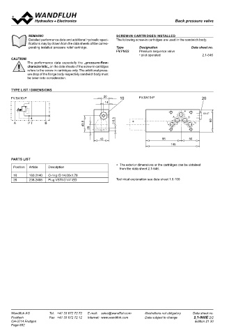
TYPE LIST / DIMENSIONS There are three pressure stages to choose The resultant pressure difference displaces the considerably or for retaining pressures over a
from. The valve has an adjustable unloading main spool towards the spring and the valve period of time, e.g. for clamping processes.
FV.SA10-P 10 FV.SA10-P 20 point and a defined re-switching difference. switches to unloading circulation. Because of Mini-4 accumulator unloading valves are used
The steel bodies of the sandwich valve are the difference in section in the pilot aerea, the everywhere where lightweight, small hydraulic
phosphate coated. Steel cartridge body and pilot flow is interrupted as soon as the pressure control systems are required. Note: An addi-
adjustment spindle galvanised to protect them in the accumulator drops by 15 % or 25 % of tional relief valve for system protection must
against corrosion. The aluminium knob has the upper switching point. The pressures at be installed. Please refere to the set-up and
a natural anodised finish. The quality of this the main spool are equilibrated and the spring connection exemple on page 2.
∗ product is reflected in the good performance displaces the main spool to the closed position.
data and design. The pump can now build up the system pres-
sure again as far as the unloading point and
the cycle starts again.
TYPE CODE
US S A04 - P #
PARTS LIST
Accumulator unloading valve, pilot operated
∗ The exterior dimensions or the cartridges can be obtained
Position Article Description from the data sheet 2.1-546. Type of adjustment Key S
Control knob D
10 160.2140 O-ring ID 14,00x1,78 ∗
20 238.2406 Plug VSTI G1/4"-ED Technical explanation see data sheet 1.0-100 Sandwich construction
Mounting interface acc. to Wandfluh standard, NG4-Mini
Type list / function in P
Pressure range p N 100 bar 100
160 bar 160
350 bar 350
Design-Index (Subject to change)
GENERAL SPECIFICATIONS HYDRAULIC SPECIFICATIONS
Description Pilot operated accumulator unloading valve Fluid Mineral oil, other fluid on request
Norminal size NG4-Mini acc. to Wandfluh standard Contamination efficiency ISO 4406:1999, class 18/16/13
Construction Sandwich construction (Required filtration grade ß6…10≥75)
Mounting 3 holes for socket cap screw M5 refer to data sheet 1.0-50/2
or studs M5 Viskosity range 12 mm /s…320 mm /s
2
2
Connections Connection plates Fluid temperature -20…+70 °C
Multi-station flange subplate Peak pressure p max = 400 bar
Longitudinal stacking system Norminal pressure p = 100 bar, p = 160 bar, p = 350 bar
N
N
N
Mounting position any Minimum pressure p = 50 bar for p 160 / 350 bar
N
min
Ambient temperature -20...+50 °C p = 25 bar for p 100 bar
min
N
Fastening torque M = 5,5 Nm (qual 8.8) for fixing screw Diff. unloading/loading 15 ± 3 % for p = 160 / 350 bar
D
N
M = 50 Nm for screw cartridge 25 ± 3 % for p = 100 bar
D
N
Weight m = 1,4 kg Volume flow Q = 1…8 l/min
min
(over 8 l/min on request)
Leakage volume flow Maximum 4 drops/min
in accumulator operation P - T
For further hydraulic characteristics refer to data sheet: 2.1-548
Wandfluh AG Tel. +41 33 672 72 72 E-mail: sales@wandfluh.com Illustrations not obligatory Data sheet no. Wandfluh AG Tel. +41 33 672 72 72 E-mail: sales@wandfluh.com Illustrations not obligatory Data sheet no.
Postfach Fax +41 33 672 72 12 Internet: www.wandfluh.com Data subject to change 2.1-860E 2/2 Postfach Fax +41 33 672 72 12 Internet: www.wandfluh.com Data subject to change 2.1-920E 1/2
CH-3714 Frutigen Edition 21 30 CH-3714 Frutigen Edition 03 35
Page 882