
Page 881 - Softbound_Edition_19_en
P. 881
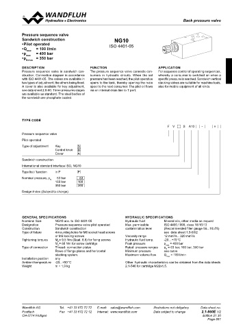
Back pressure valve
 Pressure sequence valves                                                                Pressure sequence valves


 REMARK!  SCREW-IN CARTRIDGES INSTALLED  Pressure sequence valve
 Detailed performance data and additional hydraulic speci-  The following screw-in cartridges are used in the sandwich body:  Sandwich construction  NG10
 fications may by drawn from the data sheets of the corres-  • Pilot operated
 ponding installed pressure relief cartridge.  Type   Designation   Data sheet no.  ISO 4401-05
 FV.PM22   Pressure sequence valve  • Q max   = 100 l/min
    • pilot operated   2.1-546  • p max    = 400 bar
 CAUTION!   • p     = 350 bar
 The performance data especially the  „pressure-flow-  N max
 characteristic„ on the data sheets of the screw-in catridges
 refere to the screw-in cartridges only. The additional press-  DESCRIPTION  FUNCTION  APPLICATION
 ure drop of the flange body respectivly sandwich body must   Pressure sequence valve in sandwich con-   The pressure sequence valve connects con-  For sequence control of operating sequences,
 be taken into consideration.  struction. Connection diagram in accordance   sumers in hydraulic circuits. When the set   whereby a consumer is switched on when a
            with ISO 4401-05. The valves are available in   pressure has been reached, the pilot operation   specific pressure is reached. Sandwich vertical
            two types of adjustment, the others being fixed.   opens to the tank, thereby opening the main   stacking valves are suitable for machine tools,
            A cover is also available for key adjustment,   spool to the next consumer. The pilot oil flows   also for mobile equipment of all kinds.
 TYPE LIST / DIMENSIONS  see data sheet 2.0-50. Three pressures stages   via on internal drain line to T port.
 FV.SA06-P  FV.SA06-P  are available as standard. The steel bodies of
 10  20     the sandwich are phosphate coated.


 ∗
            TYPE CODE
                                                                                       F  V    S  A10   -      #
            Pressure sequence valve
            Pilot operated
            Type of adjustment   Key     S
                             Control knob   D
                             Cover       A
 PARTS LIST
            Sandwich construction
 ∗  The exterior dimensions or the cartridges can be obtained
 Position   Article   Description    from the data sheet 2.1-546.  International standard interface ISO, NG10
 ∗
 10   160.2093   O-ring ID 9,25x1,78  Technical explanation see data sheet 1.0-100  Type list / function   in P   P
 20   238.2406   Plug VSTI G1/4"-ED  Nominal pressure, p    63 bar     63
                           N   160 bar   160
                             350 bar     350
            Design-Index (Subject to change)


            GENERAL SPECIFICATIONS                               HYDRAULIC SPECIFICATIONS
            Norminal Size    NG10 acc. to ISO 4401-05            Hydraulic fluid     Mineral oils, other media on request
            Designation      Pressure sequence valve pilot operated  Max. permissible   ISO 4406:1999, class 18/16/13
            Construction     Sandwich construction               contamination level   (Recommended filter gauge ß6...10≥75)
            Type of fixture   4 mounting holes for M6 socket head screws             see  data sheet 1.0-50/2
                             or M6 locking screws                Viscosity range     12 mm /s…320 mm /s
                                                                                                   2
                                                                                          2
            Tightening torques   M = 9,5 Nm (Qual. 8.8) for fixing screws  Hydraulic fluid temp.   -20…+70 °C
                               D
                             M = 60 Nm for screw cartridge       Peak pressure       p max  = 400 bar
                               D
            Type of connection   Thread- connection plates       Rated  pressure ranges   p  = 63 bar, 160 bar, 350 bar
                                                                                      N
                             Rows of flange plates and horizontal    Minimum pressure   see curve
                             stacking system.                    Maximum volume flow   Q max  = 100 l/min
            Installation position   any
            Ambient temperature   -20...+50 °C                   Other  hydraulic characteristics can be obtained from the data sheets
            Weight           m = 1,9 kg                          2.1-546 for cartridge M22x1,5.


 Wandfluh AG   Tel.  +41 33 672 72 72   E-mail:  sales@wandfluh.com   Illustrations not obligatory   Data sheet no.   Wandfluh AG   Tel.  +41 33 672 72 72   E-mail:  sales@wandfluh.com   Illustrations not obligatory   Data sheet no.
 Postfach   Fax  +41 33 672 72 12   Internet:  www.wandfluh.com   Data subject to change   2.1-840E 2/2   Postfach   Fax  +41 33 672 72 12   Internet:  www.wandfluh.com   Data subject to change   2.1-860E 1/2
 CH-3714 Frutigen                   Edition 21 30  CH-3714 Frutigen                                      Edition 21 30
                                                                                                            Page 881