
Page 809 - Softbound_Edition_19_en
P. 809
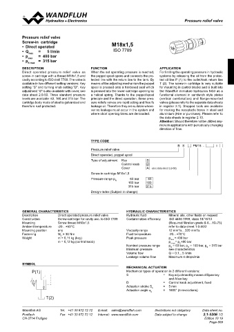
Pressure relief valve
                                                                                              Pressure relief valves


            Pressure relief valve
            Screw-in  cartridge                           M18x1,5
            •  Direct operated
            •  Q max    =      5 l/min                     ISO 7789
            •  p max    =  400 bar
            •  p N max   =  315 bar

            DESCRIPTION                        FUNCTION                           APPLICATION
            Direct operated pressure relief valve as     When the set operating pressure is reached,   For limiting the operating pressure in hydraulic
            screw-in cartridge with a thread M18x1,5 and   the poppet spool opens and connects the pro-  systems by releasing the oil from the protec-
            cavity according to ISO draft 7789. The valve is   tected line with the return line to the tank. By   ted oil line P (1) to the outlet/tank return line
            available in two different setting versions: Key   means of the adjusting mechanism the poppet   T (2). The screw-in cartridge is very suitable
            setting "S" and turning knob setting "D". Key   spool is pressed onto a hardened seat which   for mounting in control blocks and is built into
            adjustment "S" is also available with cover, see   is pressed into the lower cartridge opening by   the Wandfluh miniature hydraulics NG3 as a
            data sheet 2.0-50. Three standard pressure   a helical spring. Thanks to the poppet/spool   functional  element  in  sandwich  style  plates
            levels are available: 63, 160 and 315 bar. The   principle and the direct operation, these pres-  (vertical  combination)  and  flange-mounted
            cartridge body made of steel is galvanized and   sure reliefe valves are rapid acting and free fo     valves (please refer to the separate data sheets
            therefore rust-protected.          leakage oil. Therefore they are suitable where-  in register 2.1). Stepped tools are available
                                               ver no leakage must occur in the system and   for making the receptacle bores in steel and
                                               where short opening times are demanded.  aluminium (Hire or purchase). Please refer to
                                                                                  the data sheets in register 2.13.
                                                                                  Attention: Should therefore not be utilized any-
                                                                                  more in applications with periodically changing
                                                                                  direction of flow.


                                               TYPE CODE
                                                                                                 B   S     PM18  -      #
                                               Pressure relief valve
                                               Direct operated, poppet spool
                                               Type of adjustment   Key     S
                                                               Control knob   D
                                                               Cover        A    (see data sheet 2.0-50)
                                               Screw-in cartridge M18x1,5
                                               Pressure range p N   63 bar   63
                                                                  160 bar   160
                                                                  315 bar   315
                                               Design-Index (Subject to change)


            GENERAL CHARACTERISTICS                              HYDRAULIC CHARACTERISTICS
            Description       Direct operated pressure relief valve  Hydraulic fluid   Mineral oils, other fluids on request
            Construction      Screw-cartridge for cavity acc. to ISO 7789  Contamination efficiency   ISO 4406:1999, class 18/16/13
            Mounting          Screw thread M18x1,5                                     (Required filtration grade ß 6…10≥75)
            Ambient temperature   -20…+50°C                                            refer to data sheet 1.0-50/2
                                                                                            2
                                                                                                     2
            Mounting position   any                              Viscosity range       12 mm /s…320 mm /s
            Fastening         M  = 30 Nm                         Fluid temperature     -20…+70°C
                                D
            Weight            m = 0,11 kg (key)                  Peak pressure         p max  = 400 bar
                              m = 0,12 kg (control knob)                               p Tmax = p +80 bar
                                                                                            P
                                                                 Nominal pressure range   p = 63 bar, p = 160 bar, p = 315 bar
                                                                                                 N
                                                                                        N
                                                                                                          N
                                                                 Minimum pressure      see characteristics
                                                                 Volume flow           Q = 0,1…5 l/min
                                                                 Leakage volume flow   Maximum 4 drops/min
            SYMBOL
                                                                 MECHANICAL ACTUATION
                 P(1)                                            Mechanical types of operation in 2 different versions:
                                                                 S                  =  Key adjustment by means of Span key
                                                                                       and Allen key
                                                                 D                  =  Control knob adjustment, fixed
                                                                 Actuation stroke S     =   5 mm
                                                                              b
                                                                 Actuation angle α      =  1800° (5 revolutions)
                                                                              b
                        T(2)
            Wandfluh AG         Tel.  +41 33 672 72 72   E-mail:  sales@wandfluh.com   Illustrations not obligatory   Data sheet no.
            Postfach            Fax  +41 33 672 72 12   Internet:  www.wandfluh.com   Data subject to change   2.1-520E 1/2
            CH-3714 Frutigen                                                                             Edition 10 19
                                                                                                            Page 809
                                                    20        Ø  26

                               Ø  17           30
                                  s4
                                              40

                                     s13
                        44,6                         52

                                       s19
                                       ø23
                                      M18x1,5  50

                        30
                                              60


                                              70