
Page 807 - Softbound_Edition_19_en
P. 807
BV.PM18
Pressure relief valve
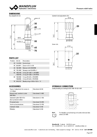
DIMENSIONS
Key adjustment «S» Control knob adjustment «D»
30
40 20
50
Cover «A»
60
70
25
PARTS LIST
Position Article Description
20 114.2224 Control knob
25 032.0611 Cover rd 23 / 3 x 35
30 193.1061 Retainer rd 6 DIN 6799
40 153.1402 Hexagon nut 0,5d M8 x 1
50 160.2156 O-ring ID 15,60 x 1,78 (NBR)
160.6156 O-ring ID 15,60 x 1,78 (FKM)
60 160.2093 O-ring ID 9,25 x 1,78 (NBR)
160.6092 O-ring ID 9,25 x 1,78 (FKM)
70 049.3137 Backup ring rd 10,6 x 13,5 x 1,4
ACCESSORIES HYDRAULIC CONNECTION
Types of adjustment for screw-in Data sheet 2.0-50 Cavity drawing according to ISO 7789–18–02–0–98
cartridges
M18x1.5
Flange body / sandwich plate Data sheet 2.1-600
NG3-Mini
Sandwich plate NG3-Mini Data sheet 2.1-700
(back pressure valve) (2)
Threaded body Data sheet 2.9-200
Technical explanations Data sheet 1.0-100 (1)
Hydraulic fluids Data sheet 1.0-50
Filtration Data sheet 1.0-50 (1)
Note! For detailed cavity drawing and cavity tools see data
sheet 2.13-1001
Wandfluh AG Postfach CH-3714 Frutigen
Tel. +41 33 672 72 72 Fax +41 33 672 72 12 sales@wandfluh.com
www.wandfluh.com Illustrations are not binding Data subject to change 3/3 Edition: 16 42 2.1-510 E
Page 807