
Page 812 - Softbound_Edition_19_en
P. 812
BESPU08
Pressure relief valve Pressure relief valve
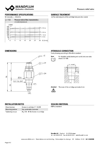
PERFORMANCE SPECIFICATIONS SURFACE TREATMENT Pressure relief cartridge
Oil viscosity u = 30 mm /s ◆ The external parts of the cartridge body are zinc coated ◆ pilot operated M22 x 1,5
2
p = f (Q) Pressure volume flow characteristics ◆ p = 400 bar ISO 7789
max
at nominal pressure ◆ p N max = 350 bar
◆ Q = 100 l/min
max
p [bar]
400 K4145
350 P N = 350 bar
300 DESCRIPTION APPLICATION
250
200 P N = 220 bar Pilot operated pressure relief valve in screw-in cartridge construc- These valves are used for limiting the operating pressure in the
150 P N = 135 bar tion for cavity according to ISO 7789. High flow capacity, very hydraulic system or for protection against pressure peaks. Can be
100 P N = 60 bar sensitively adjustable. If the pressure in P (1) exceeds the adjusted used in double pressure relief switches. The screw-in cartridge is
50
0 value of the valve, the excessive pressure is drained to T (2). Rapid perfectly suitable for installation in control blocks and is installed in
0 5 10 15 20 25 30 Q [l/min] switching with low hysteresis and excellent stability over the who- sandwich- (vertical stacked systems) and in flange plates (corres-
le flow range. The small clearance of the hardened spool ensures a ponding data sheets in this register). For machining the cartridge
low leakage volume flow. cavity in steel and aluminum blocks, cavity tools are available (hire
or purchase). Please refer to the data sheets in register 2.13.
DIMENSIONS HYDRAULIC CONNECTION Attention! As of design index #2, applications with periodically
Cavity drawing according to Wandfluh standard changing flow direction are admitted.
s5 Note! For detailed cavity drawing and cavity tools see data
sheet 2.13-1043
s19
¾“ - 16 UNF SYMBOL ACTUATION
Actuation Adjustment spindle M8 x 1
T (2) Execution S = blockable key adjustment
45 D = blockable knob adjustment
s24 (2) Optionally:
K = lockable adjustment
78 Ø24 P (1) G = star handle adjustment
→ see Data sheet 2.0-50
3/4"-16 UNF Actuation angle a = 1800 ° (5 rotations)
(1) b
2(T) Actuation stroke S = 5 mm
33 b
Attention! The nose of the cartridge protrudes 4 mm
TYPE CODE
1(P)
B V PM22 - - # 2
Pressure relief valve
Pilot operated
INSTALLATION NOTES SEALING MATERIAL Type of adjustment Key S
Control knob
D
Mounting type Screw-in cartridge ⁄4 “-16 UNF NBR as standard Cover A
3
Mounting position Any, preferably horizontal
Tightening torque M = 40 - 45 Nm Screw-in cartridge Screw-in cartridge M22 x 1,5
D
Nominal pressure range p N 63 bar 63
160 bar 160
350 bar 350
Sealing material NBR
FKM (Viton) D1
NBR 872 y-Z604
Design index (subject to change)
2.1-530
Wandfluh AG Postfach CH-3714 Frutigen
Tel. +41 33 672 72 72 Fax +41 33 672 72 12 sales@wandfluh.com
www.wandfluh.com Illustrations are not binding Data subject to change 2/2 Edition: 16 43 2.1-523 E www.wandfluh.com Illustrations are not binding Data subject to change 1/3 Edition: 18 40 2.1-530 E
Page 812