
Page 811 - Softbound_Edition_19_en
P. 811
BESPU08
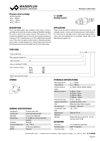
Pressure relief valves Pressure relief valve
CHARACTERISTICS Oil viscosity υ = 30 mm /s Pressure relief cartridge
2
p = f (Q) Pressure volume flow characteristics p = f (Q) Pressure volume flow characteristics ◆ direct operated ¾“-16 UNF
(Maximal adjustable pressure) (Minimal adjustable pressure) ◆ p = 350 bar Wandfluh standard
max
p [bar] p [bar] ◆ p = 350 bar
N max
400 K0672 10 K0673 ◆ Q = 30 l/min
P N = 315 bar max
30 300 7,5
200 P N = 160 bar 5 DESCRIPTION APPLICATION
100 P N = 63 bar 2,5 Direct operated poppet type pressure relief valve in screw-in These valves are used for limiting the operating pressure in the
cartridge construction for cavity according to Wandfluh standard. hydraulic system. Can be used in double pressure relief switches.
0 0 The valve is closed in the neutral position. If the pressure in P (1) For machining the cartridge cavity in steel and aluminum blocks,
0 1 2 3 4 5 Q [l/min] 0 1 2 3 4 5 Q [l/min]
p = f (n) Pressure adjustment characteristics exceeds the adjusted value of the valve, the excessive pressure is cavity tools are available (hire or purchase). Please refer to the
(at Q = 1 l/min) drained to T (2). The back pressure at T (2) is added to the adjusted data sheets in register 2.13.
P(1) p [bar] value. T (2) can be charged up to the maximum. Hardened precision
400 K0113_1 parts ensure virtually leakage-free closing. Rapid switching with
P N = 315 bar low hysteresis and excellent stability over the whole flow range.
300
200 P N = 160 bar TYPE CODE
T(2)
100
P N = 63 bar B E S PU08 - #
0 Pressure relief valve
0 1 2 3 4 5 n [-]
Direct operated, leakage-free
DIMENSIONS
Screw adjustment "S" Knob adjustment "D" Type of adjustment key
20 Ø 26 Cavity drawing to Screw-in cartridge 3/4“-16 UNF
ISO 7789–18–02–0–98
Ø 17 30 Nominal pressure range p N 60 bar 60
s4 M18x1,5 135 bar 135
40 220 bar 220
350 bar 350
s13 (2) Design index (subject to change)
2.1-523
44,6 52 SYMBOL HYDRAULIC SPECIFICATIONS
s19
(1) Working pressure p = 350 bar
ø23 (T) 2 Tank pressure p max = 350 bar
T max
M18x1,5 50 (1) Nominal pressure p = 60 bar, 135 bar, 220 bar, 350 bar
Detailed cavity drawing and cavity range N
30 tools see data sheet 2.13-1001.
60 (P) 1 Minimum pressure P 60 bar = 15 bar
N
P 135 bar = 25 bar
N
P 220 bar = 50 bar
70 P 350 bar = 120 bar
N
N
Volume flow range Q = 0,1…30 l/min
Leakage volume flow Leakage free 0,25 cc / min
Fluid Mineral oil, other fluid on request
PARTS LIST ACCESSORIES
2
2
Pressure relief valve: Viscosity range 7,4 mm /s…420 mm /s
Position Article Discription Flange-/sandwich plate NG3-Mini Data sheet 2.1-600 GENERAL SPECIFICATIONS Temperature range -20…+70 °C
Back pressure valve: fluid
20 114.2224 Knob Sandwich plate NG3-Mini Data sheet 2.1-700 Designation Pressure relief valve
30 193.1061 Safety plate RD6 DIN 6799 Construction Direct operated seat tight Contamination Class 18 / 16 / 13
40 153.1402 Hexagonal nut 0,5D M8x1 Line mount body Data sheet 2.9-200 Mounting Screw-in cartridge type efficiency
50 160.2156 O-ring ID 15,6x1,78 Nominal size ¾“-16 UNF according to Wandfluh Filtration Required filtration grade ß 10…16 ≥ 75,
60 160.2093 O-ring ID 9,25x1,78 see data sheet 1.0-50
70 49.3137 Back-up ring RD 10,6x13,5x1,4 standard
Actuation Manually ACTUATION
Ambient temperature -30…+110 °C Actuation S = lockable key adjustment
Technical explanation see data sheet 1.0-100 Weight 0,145 kg key adjustment Actuation angle 2520 ° (7 rotations)
MTTFd 150 years Actuation stroke 7 mm
Wandfluh AG Tel. +41 33 672 72 72 E-mail: sales@wandfluh.com Illustrations not obligatory Data sheet no.
Postfach Fax +41 33 672 72 12 Internet: www.wandfluh.com Data subject to change 2.1-520E 2/2 www.wandfluh.com Illustrations are not binding Data subject to change 1/2 Edition: 16 43 2.1-523 E
CH-3714 Frutigen Edition 10 19
Page 811