
Page 804 - Softbound_Edition_19_en
P. 804
A P T B
A P T B
A P T B
A P T B
P (1)
P (2)
x (1)
A P T B
A P T B
A P T B
A P T B
T (3)
T (2)
P (1)
P (1)
A P T B
A P T B
A P T B
A P T B
A P T B
P (1)
P (2)
P (1)
P (2)
x (3)
x (1)
x (1)
T (2)
T (2)
A P T B
A P T B
A P T B
A P T B
A P T B T (3)
T (2)
P (1)
P (1)
T (2)
P (1)
P (1)
P (1)
P (1)
A P T B
x (3)
A P T B
A P T B
A P T B
A P T B
T (2)
T (2)
x (3)
x (3)
B
T (2)
T (2)
T (2)
T (2)
A P T B
P
T
A P T B
P (1)
P (1)
A P T B
P (1)
P (1)
A
A P T B
x (3)
A P T B
x (3)
A P T B
T (2)
T (2)
T (2)
B T (2) A P T B T (3) A P T B A P T B
B
A P T B
A P T B A P T B
P T
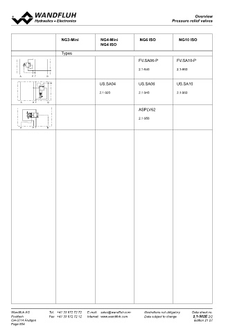
Overview
P T Over-view
Pressure relief valves BV.PM18
Pressure relief valves
A
A
A P T B A P T B
A P T B Pressure relief cartridge
NG3-Mini NG4-Mini NG6 ISO NG10 ISO ◆ pilot operated M18 x 1,5
NG4 ISO ◆ p = 400 bar ISO 7789
max
◆ p N max = 350 bar
A P T B Types ◆ max
A P T B Q = 25 l/min
A P T B
A P T B FV.SA10-P
FV.SA06-P
2.1-840 2.1-860
A P T B
A P T B
A P T B A P T B
US.SA04 US.SA06 US.SA10 DESCRIPTION APPLICATION
Pilot operated pressure relief valve in screw-in cartridge construc- These valves are used for limiting the operating pressure in the
2.1-920 2.1-940 2.1-960
tion for cavity according to ISO 7789. High flow capacity, very hydraulic system. The screw-in cartridge is perfectly suitable for
A P T B A P T B sensitively adjustable. If the pressure in P (1) exceeds the adjusted installation in control blocks and is installed in sandwich- (vertical
A P T B A P T B
value of the valve, the excessive pressure is drained to T (2). Rapid stacked systems) and in flange plates (corresponding data sheets
ASPLV62 switching with low hysteresis and excellent stability over the in this register). For machining the cartridge cavity in steel and alu-
whole flow range. The small clearance of the hardened spool en- minum blocks, cavity tools are available (hire or purchase). Please
2.1-950 sures a low leakage volume flow. refer to the data sheets in register 2.13.
A P T B
A P T B
A P T B Attention! Not to be used in applications with periodically
A P T B
changing flow direction.
SYMBOL ACTUATION
Actuation Adjustment spindle M8 x 1
T (2)
Execution S = blockable key adjustment
D = blockable knob adjustment
Optionally:
K = lockable adjustment
P (1)
G = star handle adjustment
→ see Data sheet 2.0-50
Actuation angle a = 1800 ° (5 rotations)
b
Actuation stroke S = 5 mm
b
TYPE CODE
B V PM18 - - #
Pressure relief valve
Pilot operated
Type of adjustment Key S
Control knob D
Cover A
Screw-in cartridge M18 x 1,5
Nominal pressure range p N 63 bar 63
160 bar 160
350 bar 350
Sealing material NBR
FKM (Viton) D1
NBR 872 y-Z604
Design index (subject to change)
2.1-510
Wandfluh AG Tel. +41 33 672 72 72 E-mail: sales@wandfluh.com Illustrations not obligatory Data sheet no.
Postfach Fax +41 33 672 72 12 Internet: www.wandfluh.com Data subject to change 2.1-502E 2/2 www.wandfluh.com Illustrations are not binding Data subject to change 1/3 Edition: 16 42 2.1-510 E
CH-3714 Frutigen Edition 21 27
Page 804