
Page 121 - Softbound_Edition_19_en
P. 121
Solenoids
Solenoids Solenoid accessory
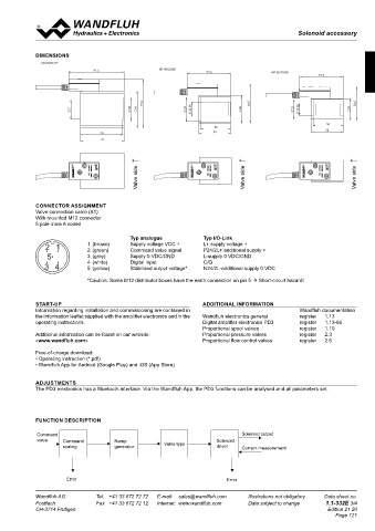
Amplifier with analogue interface DIMENSIONS 2 3 4 5 6 7 8
1
ELECTRICAL SPECIFICATIONS MT.60/31x72 MT.45/23x50
Protection class IP 67 acc. to EN 60 529 Dither Frequency adjustable 4…500 Hz 91.5 72.5 MT.35/19x50 72.5
Supply voltage IO-Link: 24 V (18..30V), analogue: 8..32V Factory setting 80 Hz A A
Residual ripple < 1.3 Vpp Level adjustable 0…400 mA
Fuse Low Factory setting 180 mA
No-load current Approx. 30 mA Temperature drift <1 % bei ∆T = 40 °C
Max. current Enable input 1 input high-active 79.5 64.5 54.5
consumption No-load current + 2,5 A per solenoid Switching threshold high 1/2 VCC +2V 31 38 60 39 23.09 45 32 19.03 35
Command value input 1 input non-differential Switching threshold low 1/2 VCC -2V
Voltage / current (switchable by means of parameter) Ramps Adjustable 0…500 s 50
0...+ 10V or 0/4...20mA IO-Link interface Data line C/Q, COM2 = 38,4 kBaud B 50 53 B
Usable as frequency input Use master type B 70 53
(frequency 5...5000 Hz) or as PWM input Bluetooth Low Energy with access protection 72
(automatic frequency detection) or digital Contains FCC ID: QOQ11
dig. switching threshold high >3V Fieldbus (option) CANopen (on request)
dig. switching threshold low <0.8V J1939 (on request) ↓ ↓ ↓
Resolution 12-bit LEDs Function green
Input resistance Voltage input >100 kΩ Bluetooth blue
Load for current input = 124 Ω IO-Link green C Valve side Valve side Valve side C
Stabilised output 5 VDC Error red
voltage max. load 20 mA Supply solenoid with IO-Link
Solenoid current: galvanically separated via P24/N24
• Minimal current I Adjustable 0…I max mA EMV 2014/53/EU (Radio Equipment Directive)
min
Factory setting 50 mA ETSI EN 300 328 CONNECTOR ASSIGNMENT
Valve connection cable (X1)
• Maximal current I max Adjustable I min ...2500 mA 47 CFR, Part 15 / ICES-003
MTS35/19x50-..-12, Factory setting 1360 mA ETSI EN 301 489-1 / 301 489-17 With mounted M12 connector
5 pole male A coded
MTS35/19x50-..-24, Factory setting 680 mA Immunity EN 61 000-6-2 D
MTS45/23x50-..-12, Factory setting 1490 mA Emission EN 61 000-6-4
MTS45/23x50-..-24, Factory setting 780 mA Typ analogue Typ I/O-Link
MTS60/31x72-..-12, Factory setting 2290 mA 2 1 1 (brown) Supply voltage VCC + L+ supply voltage +
MTA60/31x72-..-12, Factory setting 2290 mA 2 (green) Command value signal P24/2L+ additional supply +
MTS60/31x72-..-24, Factory setting 1140 mA 5 3 (grey) Supply 0 VDC/GND L-supply 0 VDC/GND Kanten nach ISO 13715 Oberflächenbeschaffenheit
MTA60/31x72-..-24, Factory setting 1140 mA 4 (white) Digital input C/Q +0.4 -0.1 Ra 3.2 Allgemein- toleranzen ISO 2768 Längenmasse, Rundungen,Fasen m Auszug Allgemeintoleranzen ISO-2768-1 >30-120
Winkel
m Nennmass
>0,5-3
>6-30
>3-6
-0.3
H
Geradheit, Ebenheit
3 4 5 (yellow) Stabilised output voltage* N24/2L-additional supply 0 VDC Rundlauf,Planlauf H Radien, ±0.2 ±0.5 ±1
Rechtwinkligkeit, Symmetrie
±0.1
±0.1
±0.3
±0.2
H Längenmasse
Material:
Fasenhöhe
Hüllbedingung nach ISO 14405 E
Gezeichnet 20.02.2019 BEH
E Geprüft 28.02.2019 FA
Freigegeben 28.02.2019 BR
*Caution: Some M12 distributor boxes have the earth connection on pin 5 Short-circuit hazard! M 1:1 Serie freigegeben Modellreferenz: Doknr. 0159119 / Konfiguration 020
Rev.
Name Änderungsnr. Änderungsbeschrieb
Datum
Gewicht
BLOCK DIAGRAM Magnetspule komplett Ersetzt durch: 0.863 kg
Ersatz für:
MT../..x..-P1... Dok.-Nr. 0247385 Format
A2
Dokument darf ohne schriftliche Einwilligung weder kopiert, Art.-Nr. Revision
verwertet noch an Dritte weitergegeben werden. DB 1.1-332 00
Zuwiderhandlung ist strafbar und wird gerichtlich verfolgt.
X2-1 1 2 3 4 5 C:\00_Wandfluh\Verkauf\Dokumentation\Reg1.1\DB 1.1-332\0247385 Blatt 1 von 1
START-UP ADDITIONAL INFORMATION
Information regarding installation and commissioning are contained in Wandfluh documentation
the information leaflet supplied with the amplifier electronics and in the Wandfluh electronics general register 1.13
operating instructions. Digital amplifier electronics PD3 register 1.13-66
M12 Proportional spool valves register 1.10
Connector pins
Additional information can be found on our website: Proportional pressure valves register 2.3
«www.wandfluh.com» Proportional flow control valves register 2.6
1 L+ Internal Supply Solenoid
supply PWM Free-of-charge download:
• Operating instruction (*.pdf)
• Wandfluh App for Android (Google Play) and iOS (App Store)
Dig
A/D
I: P24 ADJUSTMENTS
2 A: Command U/I/D *1) X2-2
A/D The PD3 electronics has a Bluetooth interface. Via the Wandfluh App, the PD3 functions can be analysed and all parameters set.
C/J: CAN_Low
3 L- CAN
FUNCTION DESCRIPTION
4 I: IO-Link C/Q Rx/Tx
A/C/J: Enable
Command Solenoid output
value Command Ramp Solenoid
A: Stab.Out scaling generator Valve type driver Current measurement
5 I: N24 *1) BLE 4x
FLASH
C/J: CAN_High RAM
Error Error
*1) fix selection according to type code
Wandfluh AG Tel. +41 33 672 72 72 E-mail: sales@wandfluh.com Illustrations not obligatory Data sheet no. Wandfluh AG Tel. +41 33 672 72 72 E-mail: sales@wandfluh.com Illustrations not obligatory Data sheet no.
Postfach Fax +41 33 672 72 12 Internet: www.wandfluh.com Data subject to change 1.1-332E 2/4 Postfach Fax +41 33 672 72 12 Internet: www.wandfluh.com Data subject to change 1.1-332E 3/4
CH-3714 Frutigen Edition 21 20 CH-3714 Frutigen Edition 21 20
Page 121