
Page 913 - Softbound_Edition_19_en
P. 913
Pressure reducing valve
Pressure reducing valve
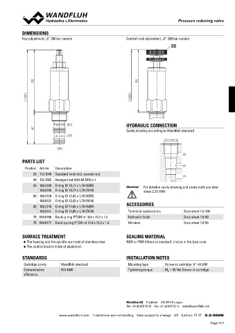
DIMENSIONS
Key adjustment „S” 200 bar version Control knob adjustment „D” 200 bar version
20
92 92
139 139
3(T) HYDRAULIC CONNECTION
47 Cavity drawing according to Wandfluh standard
2(P)
7/8"-14 UNF-2B
1(A)
(3)
PARTS LIST
(2)
Position Article Description
20 113.1049 Standard knob incl. counter nut
(1)
40 153.1505 Hexagon nut 0,8d A4 M10 x 1 (1)
50 160.2188 O-ring ID 18,77 x 1,78 (NBR) Attention! For detailed cavity drawing and cavity tools see data
160.6188 O-ring ID 18,77 x 1,78 (FKM) sheet 2.13-1045
60 160.2120 O-ring ID 12,42 x 1,78 (NBR)
160.6124 O-ring ID 12,42 x 1,78 (FKM)
65 160.2140 O-ring ID 14,00 x 1,78 (NBR) ACCESSORIES
160.6141 O-ring ID 14,00 x 1,78 (FKM) Technical explanations Data sheet 1.0-100
70 049.8166 Backup ring PTSM rd 10,8 x 13,7 x 1,4 Hydraulic fluids Data sheet 1.0-50
75 049.8177 Back-up ring PTSM rd 12,4 x 15,3 x 1,4 Filtration Data sheet 1.0-50
SURFACE TREATMENT SEALING MATERIAL
◆ The housing and the spindle are made of stainless steel NBR or FKM (Viton) as standard, choice in the type code
◆ The control knob is made of aluminium
STANDARDS INSTALLATION NOTES
Cartridge cavity Wandfluh standard Mounting type Screw-in cartridge ⁄8 “-14 UNF
7
Contamination ISO 4406 Tightening torque M = 50 Nm Screw-in cartridge
D
efficiency
Wandfluh AG Postfach CH-3714 Frutigen
Tel. +41 33 672 72 72 Fax +41 33 672 72 12 sales@wandfluh.com
www.wandfluh.com Illustrations are not binding Data subject to change 3/3 Edition: 17 27 2.2-550 E
Page 913