
Page 912 - Softbound_Edition_19_en
P. 912
Pressure reducing valve
Pressure reducing valve Pressure reducing valve
GENERAL SPECIFICATIONS HYDRAULIC SPECIFICATIONS DIMENSIONS
Designation Pressure reducing valve Working pressure p = 350 bar Key adjustment „S” 200 bar version Control knob adjustment „D” 200 bar version
max
Construction Direct operated Nominal pressure p N red = 80 bar, 200 bar 20
Mounting Screw-in cartridge construction range
Nominal size 7 ⁄8 “-14 UNF according to Wandfluh Volume flow range Q = 0…20 l/min
standard Leakage oil < 40 ml/min @ p = 200 bar, p = 315 bar
red
sys
Actuation Manually < 10 ml/min @ p = 100 bar, p = 160 bar
red
sys
Ambient temperature -25…+90 °C (NBR) Fluid Mineral oil, other fluid on request
-20…+90 °C (FKM) Viscosity range 12 mm /s…320 mm /s
2
2
Weight 0,22 kg (80 bar) Temperature range -25…+70 °C 92 92
0,32 kg (200 bar) fluid
MTTFd 150 years Contamination Class 18 / 16 / 13
efficiency 139 139
Filtration Required filtration grade ß 6…10 ≥ 75, see
data sheet 1.0-50
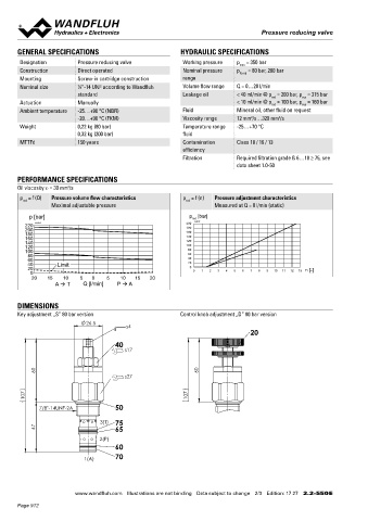
PERFORMANCE SPECIFICATIONS
Oil viscosity u = 30 mm /s
2
3(T)
p = f (Q) Pressure volume flow characteristics p = f (n) Pressure adjustment characteristics HYDRAULIC CONNECTION
red red 47
Maximal adjustable pressure Measured at Q = 0 l/min (static) Cavity drawing according to Wandfluh standard
2(P)
p [bar] p [bar] 7/8"-14 UNF-2B
red
K4157
200
K4158
220
200 180 1(A)
180 160
160 140
140 120 (3)
120 100
100 80 PARTS LIST
80 60
60 40 (2)
40 Limit 20 Position Article Description
20 0 0 1 2 3 4 5 6 7 8 9 10 11 12 13 n [-]
0 20 113.1049 Standard knob incl. counter nut (1)
20 15 10 5 0 5 10 15 20
A T Q [l/min] P A 40 153.1505 Hexagon nut 0,8d A4 M10 x 1 (1)
50 160.2188 O-ring ID 18,77 x 1,78 (NBR) Attention! For detailed cavity drawing and cavity tools see data
160.6188 O-ring ID 18,77 x 1,78 (FKM) sheet 2.13-1045
DIMENSIONS 60 160.2120 O-ring ID 12,42 x 1,78 (NBR)
Key adjustment „S” 80 bar version Control knob adjustment „D” 80 bar version 160.6124 O-ring ID 12,42 x 1,78 (FKM)
26.5 65 160.2140 O-ring ID 14,00 x 1,78 (NBR) ACCESSORIES
s4
20 160.6141 O-ring ID 14,00 x 1,78 (FKM) Technical explanations Data sheet 1.0-100
70 049.8166 Backup ring PTSM rd 10,8 x 13,7 x 1,4 Hydraulic fluids Data sheet 1.0-50
40
s17 75 049.8177 Back-up ring PTSM rd 12,4 x 15,3 x 1,4 Filtration Data sheet 1.0-50
60 60 SURFACE TREATMENT SEALING MATERIAL
s27 ◆ The housing and the spindle are made of stainless steel NBR or FKM (Viton) as standard, choice in the type code
◆ The control knob is made of aluminium
107 107
7/8"-14UNF-2A 50 STANDARDS INSTALLATION NOTES
7
Cartridge cavity Wandfluh standard Mounting type Screw-in cartridge ⁄8 “-14 UNF
3(T) 75 Contamination ISO 4406 Tightening torque M = 50 Nm Screw-in cartridge
47 65 efficiency D
2(P)
60
1(A) 70
Wandfluh AG Postfach CH-3714 Frutigen
Tel. +41 33 672 72 72 Fax +41 33 672 72 12 sales@wandfluh.com
www.wandfluh.com Illustrations are not binding Data subject to change 2/3 Edition: 17 27 2.2-550 E www.wandfluh.com Illustrations are not binding Data subject to change 3/3 Edition: 17 27 2.2-550 E
Page 912