
Page 741 - Softbound_Edition_19_en
P. 741
17 18 19 20 A
5 6 7 8
21 22 23 24 B
5 6 7 8
5 6 7 8
DIGITAL SENSOR X3
FUNCTION
ERROR 1 2 3 4 SUPPLY 1 2 3 4 1 2 3 4 A B A A B B 99 105 99 105
ERROR FUNCTION SUPPLY ERROR FUNCTION SUPPLY
USB
9 10 11 12 25 26 27 28 C USB
USB
13 14 15 16 29 30 31 32 D 9 10 11 12 C
9 10 11 12
13 14 15 16 13 14 15 16 D D C
45 114 D C
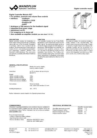
Digital controller modul
Digital amplifier module SD7 Digital controller module SD7
22,5
114
CONNECTION EXAMPLE ENHANCED AMPLIFIER
Mode of operation „Command value unipolar (2-sol)“ or „Command value unipolar (2-sol with DigInp)“ Digital Controller Module SD7 1 2 3 4 17 18 19 20
5 6 7 8
21 22 23 24
• For position, pressure and volume flow controls 5 6 7 8 1 2 3 4 17 18 19 20 1 2 3 4 1 2 3 4 17 18 19 20
1 2 3 4
• Interface: - Analogue DIGITAL SENSOR X3 5 6 7 8 21 22 23 24 5 6 7 8 5 6 7 8 21 22 23 24
- CANopen / J1939 DIGITAL SENSOR X3 DIGITAL SENSOR X3
Fuse Solenoid A Solenoid B - Profibus DP ERROR FUNCTION SUPPLY
Supply voltage + - HART ERROR FUNCTION SUPPLY ERROR FUNCTION SUPPLY ERROR FUNCTION SUPPLY ERROR FUNCTION SUPPLY
Supply voltage - USB
• Analogue or SSI sensors for the feedback signal 13 14 15 16 25 26 27 28 USB
9 10 11 12
29 30 31 32
USB
USB
• Integrated final power stage 9 10 11 12 9 10 11 12 25 26 27 28 13 14 15 16 13 14 15 16 29 30 31 32
25 26 27 28
USB
9 10 11 12
13 14 15 16
9 10 11 12
13 14 15 16
29 30 31 32
• Adjustment via PC
Command value preset • For snapping on to dome rail
with potentiometer
on analogue input 1 Error active/ Supply voltage + • Also available as amplifier module (see data sheet 1.13-101)
Solenoid A active
Enable X1-17 on Digital input 1 DESCRIPTION FUNCTION APPLICATION
on Digital input 3 Digital controller module for installation on The controller module has two Pulse- Width- As snap-on module, the controller module is
Solenoid B active
Solenoid B active dome rail for driving proportional or switching Modulated current outputs with superimposed mainly utilised in the industrial field. The
(only with mode of operation 5) X1-18 on Digital input 2 valves with one or two solenoids. Regulation dither signal. The analog and digital inputs as module can be mounted on dome rails. Thanks
on Digital input 4 of pressure, volume flow or position can be well as the digital outputs are individually pro- to numerous digital inputs and outputs, the
realized. The parameterisation takes place by grammable. With the Enhanced controller, the controller module can be connected to a
means of menu-controlled parameterisation- command value (position, pressure, force, higher-level machine control. Alternatively, the
and diagnostics software «PASO» from etc.) can also be specified by means of freely Enhanced controller can be used to control
Ramp off X1-19 Wandfluh (USB-interface). The electronics adjustable travel profiles. The fieldbus con- valves with integrated controllers (e.g. DSV,
on Digital input 5 are optionally available with different field bus nection enables reading the command value servo valves, etc.) via the analog output.
Fixed command value 1 X1-20 interfaces. signal respectively the feedback value signal
Fixed command value 2 X1-21 as well as the parameterisation directly via the
Fixed command value 4 X1-22 fieldbus.
on Digital input 6–8
Disable solenoid A X1-1
Disable solenoid B X1-2 GENERAL SPECIFICATIONS
on Digital input 1–2 Execution Module for control cubicle,
Option
Option Fieldbus housing made of plastic
Command value preset X4
and enable Master Installation on 35 mm dome rail according to
via fieldbus EN 60715
Weight
• Basic controller analog 130 g
• Basic controller fieldbus 220 g
• Enhanced controller analog 220 g
• Enhanced controller fieldbus 240 g
Connections Screw terminals,
CONNECTION EXAMPLE ENHANCED AMPLIFIER WITH HART max. cable cross-section 2,5 mm 2
Mode of operation „Command value unipolar (2-sol)“ or „Command value unipolar (2-sol with DigInp)“ Working temperature -20…+70 °C
Further information can be found in the Operating instructions.
Fuse Solenoid A Solenoid B
Supply voltage + X1-5
Supply voltage - X1-6 X1-15
X1-16
X1-13
Command value preset X1-21 X1-14 COMMISSIONING ADDITIONAL INFORMATION
and enable HART X1-22 Information regarding installation and commissioning are contained in Wandfluh documentation
via HART the information leaflet supplied with the controller module and in the Wandfluh electronics general Register 1.13
on analogue input 3 Error active/ Supply voltage + operating instructions. Further information can be found on our website: Proportional spool valves Register 1.10
Solenoid A active
www.wandfluh.com Proportional pressure valves Register 2.3
X1-3 on Digital input 1 Proportional flow valves Register 2.6
Free-of-charge download:
Solenoid B active • «PASO» Parameterisation software
X1-4 on Digital input 2 • Operating instructions (.pdf)
• Device description data: (EDS file «WAGSD7C1.eds»)
(GSD file «SD7-0B8E.gsd»)
Fuse Solenoid A
Supply voltage + X1-5
Wandfluh AG Supply voltage - sales@wandfluh.com Illustrations not obligatory Data sheet no. Wandfluh AG Tel. +41 33 672 72 72 sales@wandfluh.com Illustrations not obligatory Data sheet no.
Tel. +41 33 672 72 72
X1-6
X1-15
Postfach Fax +41 33 672 72 12 www.wandfluh.com Data subject to change 1.13-101E 10/10 Postfach Fax +41 33 672 72 12 www.wandfluh.com Data subject to change 1.13-106E 1/11
X1-16
CH-3714 Frutigen Solenoid B Edition 23 02 CH-3714 Frutigen Edition 23 02
Page 741
Command value preset X1-21
and enable HART X1-22 X1-14
via HART
on analogue input 3 Error active/ Supply voltage +
Solenoid A active
X1-3 on Digital input 1
Solenoid B active
X1-4 on Digital input 2