Page 744 - Softbound_Edition_19_en
P. 744

1 2 3 4
                                                                                                      21 22 23 24
                                                                                                5 6 7 8
                                                                                                       DIGITAL SENSOR X3
                                                                                                  FUNCTION
                                                                                                 ERROR
                                                                                                       FIELDBUS X4
                                                                                                  USB SUPPLY  17 18 19 20  A B                 A     B         99  105
                                                                                                9 10 11 12 25 26 27 28  C
                                                                                                13 14 15 16 29 30 31 32  D
                                                                                                                                                D    C
                                                                                                     45                                  114
                                                                                 Digital controller module SD7
                                                                                      Digital controller modul
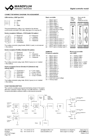
       CONNECTOR WIRING DIAGRAM / PIN ASSIGNMENT
       USB-interface, USB Type B X2                      Basic controller             - Basis   - Basis controller
                                                                                        controller  fieldbus
                  1  =  VBUS                               1  =  Digital input 1        Analog   - Enhanced controller
                9    5  6   1                              2  =  Digital input 2                                                   A    B
                     4
        3  2    8  2  =  D - 7  2 3                        3  =  Digital output 1
                     3
                                                                                                       A
                                                                                                1 2 3
        4  1    7    2  8   4                                                          1 2 3 4  1 2 3 4 4  17 18 19 20
                6  3  =  D+ 9  5                           4  =  Digital output 2      5 6 7 8  5 6 7 8 8  21 22 23 24
                                                                                                5 6 7
                                                                                                       B
                     1
                  4  =  GND                                                                                        1 2 3 4                           1 2 3 4  17 18 19 20
                                                           5  =  Supply voltage+                                   5 6 7 8  17 18 19 20              5 6 7 8  21 22 23 24
       The parameterisation cable is not included in the delivery    6  =  Supply voltage 0 VDC                          21 22 23 24
       (commercially available USB cable, plug type A to plug type B)    7  =  Stabilised output voltage
                                                           8  =  Analog ground                         DIGITAL SENSOR X3
       Device receptacle CANopen, J1939 (male) X4 (option)    9  =  Analog input 1+                                       DIGITAL SENSOR X3                  DIGITAL SENSOR X3
                                                         10  =  Analog input 1 -
                  1  =  Reserved     6 =  Reserved       11  =  Analog input 2+                                                                     99  105
   5          1
 9     6          2  =  CANLow       7 =  CANHigh        12  =  Analog input 2 -        ERROR  FUNCTION  SUPPLY  ERROR  FUNCTION  FUNCTION  SUPPL
 3  2  8  4 3  7  2 3  3  =  CANGnd   8 =  Reserved      13  =  Output solenoid driver 2 +       ERROR  SUPPLYY  FIELDBUS X4  FUNCTION                  FUNCTION  SUPPLY
 4  1  7  2  8  4  4  =  Reserved    9 =  Reserved       14  =  Output solenoid driver 2  -                         ERROR  SUPPLY                      ERROR  FIELDBUS X4
 6  1  9      5   5  =  CANShield                        15  =  Output solenoid driver 1 +                                FIELDBUS X4
                                                         16  =  Output solenoid driver 1  -  USB  USB
                                                                                                  USB
       The mating connector (plug female, DSUB, 9-pole) is not included    21  =  HART (option) Analog input 3 +  9 10 11 12  9 10 11 12 C  USB        USB
                                                                                                9 10 11 12 25 26 27 28
                                                                                                                                                     9 10 11 12 25 26 27 28
                                                                                                13 14 15 16
       in the delivery                                   22  =  HART (option) Analog input 3 -  13 14 15 16  13 14 15 16 29 30 31 32  9 10 11 12 25 26 27 28  13 14 15 16 29 30 31 32
                                                                                                      D
                                                                                                                   13 14 15 16 29 30 31 32
                                                                                                                                    D   C
       Device receptacle Profibus (female) X4 (option)                                           22,5                         114
                                                         Additional                   Enhanced controller
                  1  =  Reserved     6 =  VP
                        1
       9      5  6 2  =  Reserved    7 =  Reserved       Enhanced controller          with HART
                        2
 3  2  8      4 3  7 3  =  RxD / TxD - P   8 =  RxD / TxD - N  17  =  Digital input 3  17  =  Analog output +
                        3
 4  1  7      2  8 4  =  Reserved    9 =  Reserved       18  =  Digital input 4       18  =  Analog output -
                        4
       6         9
                        5
              1   5  =  DGND                             19  =  Digital input 5       19  =  Digital input 3
                                                         20  =  Digital input 6       20  =  Digital input 4
       The mating connector (plug male, DSUB, 9-pole) is not included    21  =  Digital input 7  21  =  Analog input 3 + HART
       in the delivery.                                  22  =  Digital input 8       22  =  Analog input 3 - HART
                                                         23  =  Digital output 3      23  =  Analog input 4 +
       Device receptacle Sensor (female) X3 (Enhanced only    24  =  Digital output 4  24  =  Analog input 4 -                             1 2 3 4
                                                                                           1 2 3 4
       without HART)                                     25  =  Analog input 3 +           5 6 7 8                                          5 6 7 8
                  1  =  Digital input +   6  =  Clock output -   26  =  Analog input 3 -
              5          1                               27  =  Analog input 4 +
       9          6 2  =  Digital input –    7  =  Output +5VDC
 3  2         4          2                               28  =  Analog input 4 -
       8      3   7 3  =  Reserved    8  =  Sensor ground
                         3
 4  1  7      2   8 4  =  Reserved    9  =  Output +24VDC   29  =  Digital ground
       6          9      4                               30  =  Analog ground
              1   5  =  Clock output +                   31  =  Stabilised output voltage
                         5
       The mating connector (plug male, DSUB, 9-pole) is not included    32  =  Analog output  ERROR  FUNCTION  SUPPLY                       ERROR  FUNCTION  SUPPLY
       in the delivery.
       FUNCTION DESCRIPTION                                                                  USB
                                                                                           9 10 11 12                                         USB
       The controller module can be parameterised by means of the param-                   13 14 15 16                                      9 10 11 12
       eterisation software «PASO» through the USB-interface. In addition,                                                                 13 14 15 16
       the parameterisation software makes a data analysis possible.
                                                       DigInp
                                                           Enable
                                     HOLD        Manual    Forward
                                    Command      mode      Backwards                          Solenoid output
                                       value               Rapid motion                 Solenoid
                                                                                        driver 1  Current measurement
                                       Fieldbus only
         Command
         value 1
                  Command      Fixed       Command                                  DigInp
         Command   value      command       value           Controller   Valve
         value 2   Scaling     values      generator                     type         Enable  Error
                                                                                              Solenoid output
              DigInp        DigInp      DigInp                      DigInp              Solenoid
                                                                                        driver 2  Current measurement
                Selection Error  Number   Enable                      Solenoid 2
          Command  Command                                                          DigInp
          value 1  value
                   Scaling                                                            Enable  Error
         Command
         value 2
                                           Display    Window
                     Error
       Wandfluh AG        Tel.  +41 33 672 72 72   sales@wandfluh.com     Illustrations not obligatory   Data sheet no.
       Postfach           Fax  +41 33 672 72 12   www.wandfluh.com        Data subject to change   1.13-106E 4/11
       CH-3714 Frutigen                                                                            Edition 23 02
       Page 744
   739   740   741   742   743   744   745   746   747   748   749