Page 736 - Softbound_Edition_19_en
P. 736

Digital amplifier module
                                                                                  Digital amplifier module SD7                                                                                                Digital amplifier module SD7
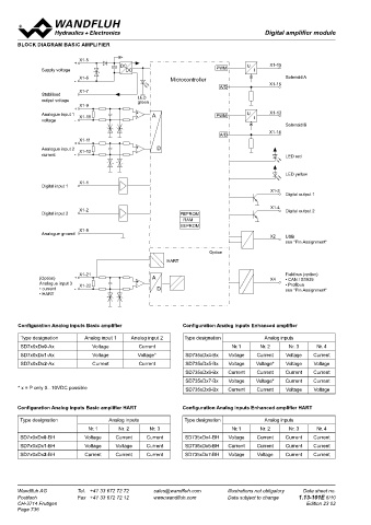
       BLOCK DIAGRAM BASIC AMPLIFIER                                                                                               BLOCK DIAGRAM ENHANCED AMPLIFIER

                          X1-5
                         +              DC                                      U       X1-15
              Supply voltage             DC                           PWM          I                                                                +  X1-5      DC                                     U    X1-15
                          X1-6                          Microcontroller                      Solenoid A                                    Supply                 DC                           PWM        I
                         -                                                              X1-16                                              voltage   X1-6               LED       Microcontroller                 Solenoid A
                                                                        A/D                                                                      0 VDC                  green                                X1-16
                          X1-7                                                                                                                                                                 A/D
              Stabilised
              output voltage                 LED                                                                                                                         Ref
                                             green
                          X1-9                                                                                                             Stabilised output  X1-7
                         +                                                                                                                 voltage                            A
              Analogue input 1  X1-10        + -  A                   PWM       U       X1-13                                                        X1-9                                      PWM      U  I  X1-13
              voltage    -                                                         I                                                                +                +                                            Solenoid B
                                                                                             Solenoid B                                   Analogue input 1  X1-10    -
                                                                                                                                                    -                            10-Bit                      X1-14
                                                                                       X1-14                                                                                                   A/D
                                                                        A/D
                          X1-11
                         +                                                                                                                           X1-11
              Analogue input 2  X1-12        + -   D                                                                                                +                +                                            LED red
              current    -                                                                   LED red                                      Analogue input 2  -  X1-12  -
                                                                                                                                                                                                                  LED yellow
                                                                                             LED yellow                                                                  Ref
                          X1-1                                                                                                            Stabilised output  X1-31                             SPI       A   X1-32  Analogue output
              Digital input 1                                                                                                             voltage                                                         D
                                                                                        X1-3                                                                                                             12-Bit
                                                                                             Digital output 1                                        X1-25
                                                                                                                                                    +
                                                                                                                                           Analogue input 3  X1-26   + -                                     X1-30
                                                                                        X1-4                                                        -                                                             Analogue ground
                          X1-2                                                               Digital output 2
              Digital input 2                              FEPROM                                                                                                         A   SPI
                                                            RAM                                                                                      X1-27                D
                                                           EEPROM                                                                                   +                    16-Bit
                          X1-8                                                                                                             Analogue input 4          +                                        X1-3  Digital output 1
              Analogue ground                                                                                                                       -  X1-28         -
                                                                                        X2   USB
                                                                                             see "Pin Assignment"                                                                                             X1-4
                                                                                                                                                                                                                  Digital output 2
                                                                    Option                                                                 Analogue ground  X1-8                                             X1-23
                                                       HART                                                                                                                                                       Digital output 3
                                                                                                                                                                                                             X1-24
                          X1-21                                                              Fieldbus (option)                                                                                                    Digital output 4
              (Option)   +                        A                                     X4   • CAN / S1939
              Analogue input 3   X1-22       + -                                             • Profibus
              • current  -                         D                                         see "Pin Assignment"
              • HART
                                                                                                                                                     X1-1
                                                                                                                                          Digital input 1
                                                                                                                                                     X1-2
                                                                                                                                          Digital input 2
       Configuration Analog inputs Basic amplifier          Configuration Analog inputs Enhanced amplifier
                                                                                                                                          Digital input 3  X1-17
        Type designation    Analog input 1  Analog input 2  Type designation          Analog inputs
        SD7x0xDx0-Ax           Voltage        Current                      Nr. 1    Nr. 2     Nr. 3    Nr. 4                              Digital input 4  X1-18
        SD7x0xDx1-Ax           Voltage       Voltage*        SD735xDx4-Bx  Voltage  Current  Voltage  Current                                        X1-19
        SD7x0xDx2-Ax           Current        Current        SD735xDx5-Bx  Voltage  Voltage*  Voltage  Voltage                            Digital input 5
                                                             SD735xDx6-Bx  Current  Current  Current  Current                                        X1-20
                                                                                                                                          Digital input 6
                                                             SD735xDx7-Bx  Voltage  Voltage*  Current  Current
       * x = P only 0...10VDC possible                       SD735xDx8-Bx  Current  Current  Voltage  Voltage                             Digital input 7  X1-21
                                                                                                                                                                                      FEPROM                    X2  USB
                                                                                                                                                                                      FEPROM
                                                                                                                                                                                       RAM
                                                                                                                                                                                       RAM
                                                                                                                                                     X1-22                                                          see "Pin Assignment"
                                                                                                                                                                                      EEPROM
       Configuration Analog inputs Basic amplifier HART     Configuration Analog inputs Enhanced amplifier HART                           Digital input 8                             EEPROM
        Type designation            Analog inputs           Type designation          Analog inputs                                       Digital ground  X1-29
                             Nr. 1     Nr. 2     Nr. 3                     Nr. 1    Nr. 2     Nr. 3    Nr. 4                                                                                 Option
        SD7x0xDx0-BH        Voltage   Current   Current     SD735xDx4-BH  Voltage  Current   Current  Current
                                                                                                                                                                                                                     Fieldbus (Option)
        SD7x0xDx1-BH        Voltage   Voltage   Current     SD735xDx6-BH  Current  Current   Current  Current                                                                                                   X4   • CAN / S1939
        SD7x0xDx2-BH        Current   Current   Current     SD735xDx7-BH  Voltage   Voltage  Current  Current                                                                                                        • Profibus
                                                                                                                                                                                                                     see "Pin Assignment"


       Wandfluh AG        Tel.  +41 33 672 72 72   sales@wandfluh.com     Illustrations not obligatory   Data sheet no.            Wandfluh AG         Tel.  +41 33 672 72 72   sales@wandfluh.com     Illustrations not obligatory   Data sheet no.
       Postfach           Fax  +41 33 672 72 12   www.wandfluh.com        Data subject to change   1.13-101E 6/10                  Postfach            Fax  +41 33 672 72 12   www.wandfluh.com        Data subject to change   1.13-101E 7/10
       CH-3714 Frutigen                                                                            Edition 23 02                   CH-3714 Frutigen                                                                             Edition 23 02
       Page 736
   731   732   733   734   735   736   737   738   739   740   741