
Page 176 - Softbound_Edition_19_en
P. 176
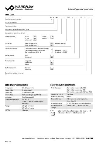
Solenoid operated spool valve
Solenoid operated spool valve Solenoid operated spool valve
TYPE CODE ACTUATION HYDRAULIC SPECIFICATIONS
WD M F A10 - - / - # Actuation Switching solenoid, wet pin push type, Working pressure p = 350 bar
max
Spool valve, direct operated pressure tight Tank pressure p = 160 bar
Tmax
Execution W.E64 / 31 x 72 (Data sheet 1.1-190) Maximum volume flow Q = 160 l/min, see characteristics
Slip-on coil, medium max
M.S60 / 31 x 72 (Data sheet 1.1-193) Leakage oil See characteristics
Flange construction Connection Connector socket EN 175301 – 803 Fluid Mineral oil, other fluid on request
Connector socket AMP Junior-Timer 2 2
International standard interface ISO, NG10 Viscosity range 12 mm /s…320 mm /s
Connector Deutsch DT04 – 2P
Temperature range -25…+70 °C (NBR)
Designation of symbols acc. to table fluid -20…+70 °C (FKM)
Contamination Class 20 / 18 / 14
Nominal votage U 12 VDC G12 115 VAC R115
N
24 VDC G24 230 VAC R230 efficiency
without coil X5 Filtration Required filtration grade ß 10…16 ≥ 75,
see data sheet 1.0-50
Slip-on coil Metal housing, round W (only G12 and G24)
Metal housing, square M
Connection execution Connector socket EN 175301-803 / ISO 4400 D PERFORMANCE SPECIFICATIONS
Connector socket AMP Junior-Timer J (only for U ≤ 75 VDC) Oil viscosity u = 30 mm /s
2
N
Connector Deutsch DT04 - 2P G (only for U ≤ 75 VDC)
N
p = f (Q) Performance limits
Sealing material NBR Measured with nominal voltage -10 %
FKM (Viton) D1
p [bar] ADB/ACB
Manual override Integrated 350 K1021
Push-button HF1 300 AGB/AB3/AFB
Spindle HS1 250
200
Surface protection Standard 150 AB1
Zinc-nickel K8 100
50 BEA
Design index (subject to change) 0
1.2-76 0 20 40 60 80 100 120 140 160 Q [l/min]
Δp = f (Q) Pressure drop volume flow characteristics Volume flow direction
Economy / Medium Symbol P - A P - B P - T A - T B - T
GENERAL SPECIFICATIONS ELECTRICAL SPECIFICATIONS p [bar] AB1 / AB2 / AB3 5 5 - 3 2
20 K1022_1 1 2 3
Designation 4/2-, 4/3-spool valve Protection class Connection execution D: IP65 4 ACB / AC1 / CB2 5 5 - 3 2
Construction Direct operated Connection execution J: IP66 15 5 ADB / AD1 / DB2 5 5 - 5 4
Mounting Flange construction Connection execution G: IP67 and IP69K 10 6 BEA / BE1 / EA2 3 3 1 3 2
Nominal size NG10 according to ISO 4401-05 Relative duty factor 100 % DF AFB / AF1 / FB2 6 6 6 5 4
Actuation Switching solenoid Switching frequency 6'000 / h 5 AGB / AG1 / GB2 6 6 - 3 2
7
Ambient temperature -25…+70 °C Service life time 10 (number of switching cycles, 0
if > +50 °C, then no undervoltage is theoretically) 0 20 40 60 80 100 120 140 160 Q [l/min]
admissible Voltage tolerance ± 10 % with regard to nominal voltage
Weight 3,90 kg (1 solenoid) Standard nominal 12 VDC, 24 VDC, 115 VAC, 230 VAC Q = f (Q) Leakage volume flow characteristics Q = f (Q) Leakage volume flow characteristics
5,40 kg (2 solenoids) voltage L per control edge L per control edge
MTTFd 150 years Note! Other electrical specifications see data sheet 1.1-190 Q [cm /min] Q [cm /min]
3
3
(slip-on coil W) and 1.1-193 (slip-on coil M) 300 K4133 300 K4134
250 250
200 200
150 150
100 100
50 50
0 0
0 50 100 150 200 250 300 350 p [bar] 0 50 100 150 200 250 300 350 p [bar]
AB1/AB3/ACB/ADB/AFB/AGB BEA
www.wandfluh.com Illustrations are not binding Data subject to change 2/5 Edition: 21 22 1.2-76 E www.wandfluh.com Illustrations are not binding Data subject to change 3/5 Edition: 21 22 1.2-76 E
Page 176