
Page 1008 - Softbound_Edition_19_en
P. 1008
Proportional pressure reducing valve
Proportional pressure reducing valve Proportional pressure reducing valve
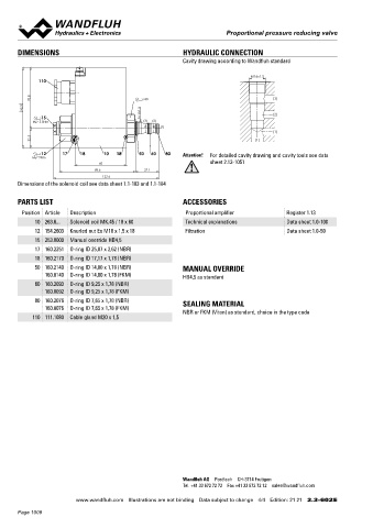
DIMENSIONS HYDRAULIC CONNECTION Proportional pressure reducing cartridge inverse
Cavity drawing according to Wandfluh standard ◆ direct operated M16 x 1,5
◆ Q = 6 l/min Wandfluh standard
max
M16x1.5 ◆ p = 210 bar (350 bar)
max
110
◆ p = 40 bar
N red max
70.8 s30 (3)
93.3
15 M16x1.5 (2) DESCRIPTION APPLICATION
MD=5.5Nm (3) (2)
(1) Direct operated proportional pressure reducing valve with inverse These valves are used in hydraulic systems where the pressure
(1) function in screw-in cartridge construction for cavity according to has to be changed frequently. The electrical remote control in
22.5 (1) Wandfluh standard. The proportional pressure reducing valve conjunction with process controls allows economical solutions
controls the pressure in port A (1). With the solenoid deenergised, with repeatable processes. For machining the cartridge cavity in
12 17 18 10 18 50 60 80 Attention! For detailed cavity drawing and cavity tools see data
MD=9Nm maximum working pressure is present. If the solenoid current steel and aluminum blocks, cavity tools are available (hire or
60 sheet 2.13-1051 increases, the pressure in port A drops (1). The valve operates purchase). Please refer to the data sheets in register 2.13.
88.6 27.1 practically independently of the pressure in port P (2). Pressure
122.6 increase in port A (1) to above the adjusted value, e.g. through an
Dimensions of the solenoid coil see data sheet 1.1-183 and 1.1-184 active consumer, is avoided by discharging excess oil to the tank
(3). For the control, Wandfluh proportional amplifiers are available
PARTS LIST ACCESSORIES (see register 1.13).
Position Article Description Proportional amplifier Register 1.13
10 263.6... Solenoid coil MK.45 / 18 x 60 Technical explanations Data sheet 1.0-100
12 154.2603 Knurled nut Ex M18 x 1,5 x 18 Filtration Data sheet 1.0-50
15 253.8000 Manual override HB4,5
17 160.2251 O-ring ID 25,07 x 2,62 (NBR)
18 160.2170 O-ring ID 17,17 x 1,78 (NBR) SYMBOL ACTUATION
50 160.2140 O-ring ID 14,00 x 1,78 (NBR) MANUAL OVERRIDE
160.8140 O-ring ID 14,00 x 1,78 (FKM) HB4,5 as standard (A) 1 Actuation Proportional solenoid, wet pin push
type, pressure tight
60 160.2093 O-ring ID 9,25 x 1,78 (NBR) Execution W.S37 / 19 x 50 (Data sheet 1.1-173)
160.8092 O-ring ID 9,25 x 1,78 (FKM) M.S35 / 19 x 50 (Data sheet 1.1-174)
80 160.2076 O-ring ID 7,65 x 1,78 (NBR) SEALING MATERIAL Connection Connector socket EN 175301 – 803
160.8076 O-ring ID 7,65 x 1,78 (FKM)
NBR or FKM (Viton) as standard, choice in the type code (P) 2 (T) 3 Connector socket AMP Junior-Timer
110 111.1080 Cable gland M20 x 1,5 Connector Deutsch DT04 – 2P
STANDARDS INSTALLATION NOTES
Cartridge cavity Wandfluh standard Mounting type Screw-in cartridge type M16 x 1,5
Solenoids DIN VDE 0580 Mounting position Any, preferably horizontal
Connection execution D EN 175301 – 803 Tightening torque M = 30 Nm Screw-in cartridge
D
Protection class EN 60 529 M = 5 Nm knurled nut
D
Contamination efficiency ISO 4406
Wandfluh AG Postfach CH-3714 Frutigen
Tel. +41 33 672 72 72 Fax +41 33 672 72 12 sales@wandfluh.com
www.wandfluh.com Illustrations are not binding Data subject to change 4/4 Edition: 21 21 2.3-602 E www.wandfluh.com Illustrations are not binding Data subject to change 1/4 Edition: 19 28 2.3-603 E
Page 1008