Page 1006 - Softbound_Edition_19_en
P. 1006

Proportional pressure reducing valve
                                                                         Proportional pressure reducing valve                                                                                          Proportional pressure reducing valve


       TYPE CODE                                                                                                                   PERFORMANCE SPECIFICATIONS
                                                                                                                                                    2
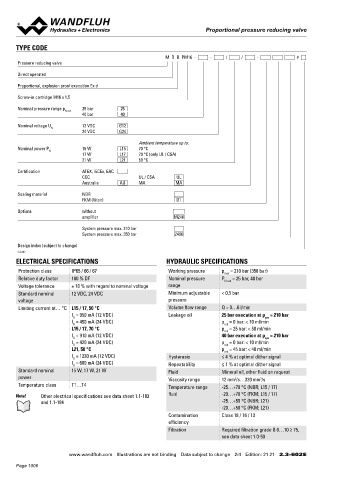
                                                           M  D  B  PM16  -     -     /     /     -           #                    Oil viscosity u = 30 mm /s
       Pressure reducing valve                                                                                                      p  = f (Q)  Pressure volume flow characteristics     p  = f (Q)  Pressure volume flow characteristics
                                                                                                                                                                                          red
                                                                                                                                     red
       Direct operated                                                                                                                        Maximal adjustable pressure                          Maximal adjustable pressure
                                                                                                                                              25 bar execution                                     40 bar execution
       Proportional, explosion proof execution Ex d                                                                                           *Limit of the operating range                        *Limit of the operating range
                                                                                                                                       p [bar]                                              p [bar]
       Screw-in cartridge M16 x 1,5
                                                                                                                                      30  K1145                                            60  K1144
       Nominal pressure range p N red    25 bar    25
                              40 bar       40                                                                                         20                                                   40

       Nominal voltage U      12 VDC       G12                                                                                                   ∗                                                ∗
                   N                                                                                                                  10                                                   20     
                              24 VDC       G24
                                                  Ambient temperature up to:                                                           0                                                    0
       Nominal power P        15 W         L15    70 °C                                                                                 6     4     2    0     2     4    6                  6     4    2     0     2    4     6
                  N
                              17 W         L17    70 °C (only UL / CSA)                                                                        A     T  Q [l/min]  P   A                         A     T  Q [l/min]  P   A
                              21 W         L21    50 °C
       Certification          ATEX, IECEx, EAC
                              CCC                 UL / CSA     UL                                                                   p  = f (n)  Pressure adjustment characteristics      p  = f (n)  Pressure adjustment characteristics
                              Australia    AU     MA           MA                                                                    red                                                  red
                                                                                                                                              Measured at Q = 0 l/min (static)                     Measured at Q = 0 l/min (static)
       Sealing material       NBR                                                                                                             25 bar execution                                     40 bar execution
                              FKM (Viton)                      D1                                                                             **Slightly increased hysteresis                      **Slightly increased hysteresis
                                                                                                                                       p [bar]                                              p [bar]
       Options                without                                                                                                 30  K4148                   L21                      50  K4149                  L21
                              amplifier                       M248
                                                                                                                                      25                                                   40
                              System pressure max. 210 bar                                                                            20                                    L15 / L17      30                                   L15 / L17
                              System pressure max. 350 bar       Z406                                                                 15
                                                                                                                                      10                                                   20
       Design index (subject to change)                                                                                                5                                                   10
       2.3-602                                                                                                                               **                                                   **
                                                                                                                                       0                                                    0
       ELECTRICAL SPECIFICATIONS                           HYDRAULIC SPECIFICATIONS                                                     0   10  20  30  40 50 60 70 80 90  100  l [%]        0   10  20  30  40 50 60 70 80 90  100  l [%]
       Protection class   IP65 / 66 / 67                    Working pressure   p  = 210 bar (350 bar)
                                                                                max
       Relative duty factor  100 % DF                       Nominal pressure   P   = 25 bar, 40 bar
                                                                                N red
       Voltage tolerance  ± 10 % with regard to nominal voltage  range
       Standard nominal   12 VDC, 24 VDC                    Minimum adjustable   < 0,5 bar                                         STANDARDS                                            SURFACE TREATMENT
       voltage                                              pressure                                                                Cartridge cavity   Wandfluh standard                 ◆  The cartridge body is gas-nitro carburised
       Limiting current at… °C L15 / 17, 50 °C              Volume flow range  Q = 0…6 l/min                                        Explosion protection  Directive 2014 / 34 / EU (ATEX)  ◆  The slip-on coil and the armature tube are zinc-nickel coated
                          I  = 950 mA (12 VDC)              Leakage oil        25 bar execution at p  = 210 bar                     Flameproof enclosure  EN / IEC / UL 60079-1, 31
                                                                                              sys
                           G
                          I  = 450 mA (24 VDC)                                 p  = 0 bar: < 10 ml/min
                           G                                                    red                                                 Cable entry        EN 60079-0, 1, 7, 15, 31
                          L15 / 17, 70 °C                                      p  = 25 bar: < 50 ml/min                             Protection class   EN 60 529
                                                                                red
                          I  = 910 mA (12 VDC)                                 40 bar execution at p  = 210 bar                     Contamination      ISO 4406
                           G
                                                                                              sys
                          I  = 420 mA (24 VDC)                                 p  = 0 bar: < 10 ml/min
                           G                                                    red                                                 efficiency
                          L21, 50 °C                                           p  = 45 bar: < 40 ml/min
                                                                                red
                          I  = 1230 mA (12 VDC)             Hysteresis         ≤ 4 % at optimal dither signal
                           G
                          I  = 600 mA (24 VDC)
                           G                                Repeatability      ≤ 1 % at optimal dither signal                      COMMISSIONING                                        INSTALLATION NOTES
       Standard nominal   15 W, 17 W, 21 W                  Fluid              Mineral oil, other fluid on request
       power                                                Viscosity range    12 mm /s…320 mm /s                                  Attention!    The solenoid coil must only be put into operation, if the   Mounting type  Screw-in cartridge type M16 x 1,5
                                                                                   2
                                                                                            2
       Temperature class  T1…T4                             Temperature range   -25…+70 °C (NBR; L15 / 17)                                  requirements of the operating instructions supplied are   Mounting position  Any, preferably horizontal
                                                                                                                                            observed to their full extent. In case of non-observance,
       Note!   Other electrical specifications see data sheet 1.1-183   fluid  -20…+70 °C (FKM; L15 / 17)                                   no liability can be assumed.                 Tightening torque  M  = 30 Nm screw-in cartridge
                                                                                                                                                                                                             D
                                                                                                                                                                                                            M  = 9 Nm Knurled nut
               and 1.1-184                                                     -25…+50 °C (NBR; L21)                                                                                                         D
                                                                               -20…+50 °C (FKM; L21)
                                                            Contamination      Class 18 / 16 / 13
                                                            efficiency
                                                            Filtration         Required filtration grade ß 6…10 ≥ 75,
                                                                               see data sheet 1.0-50
                         www.wandfluh.com  Illustrations are not binding  Data subject to change  2/4  Edition: 21 21  2.3-602 E                      www.wandfluh.com  Illustrations are not binding  Data subject to change  3/4  Edition: 21 21  2.3-602 E
       Page 1006
   1001   1002   1003   1004   1005   1006   1007   1008   1009   1010   1011