
Page 1012 - Softbound_Edition_19_en
P. 1012
Proportional pressure reducing valve
Proportional pressure reducing valve Proportional pressure reducing valve
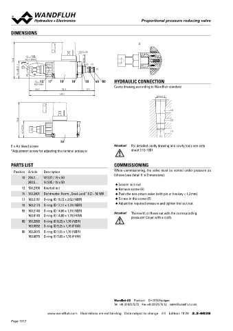
DIMENSIONS Proportional pressure reducing cartridge
◆ direct operated M16 x 1,5
X ◆ Q = 6 l/min Wandfluh standard
max
◆ p = 210 bar (350 bar)
max
s30 ◆ p N red max = 40 bar
15
76.8 MD=10Nm M16x1.5
s6
37.1 E (3) (2)
(1)
W = X * DESCRIPTION APPLICATION
12 17 10 18 50 60 80 HYDRAULIC CONNECTION Direct operated proportional pressure reducing valve in screw-in These valves are used in hydraulic systems where the pressure
MD=5Nm
Cavity drawing according to Wandfluh standard cartridge construction for cavity according to Wandfluh standard. has to be changed frequently. The electrical remote control in
34.7 78.3 27.1
Proportionally to the solenoid current, the solenoid force and the conjunction with process controls allows economical solutions
140.1
M16x1.5 pressure in port A (1) rise. The valve functions practically indepen- with repeatable processes. For machining the cartridge cavity in
dently of the pressure in port P (2). Pressure increase in the consu- steel and aluminum blocks, cavity tools are available (hire or
mer port A (1) to above the adjusted value, e.g. through an active purchase). Please refer to the data sheets in register 2.13.
(3) consumer, is avoided by discharging excess oil to the tank T (3).
With the solenoid deenergised, the oil flows freely from consumer
74.8 (2) port A (1) to port T (3). For the control, Wandfluh proportional ampli-
35 fiers are available (see register 1.13).
M = (1)
(1)
10
E = Air bleed screw Attention! For detailed cavity drawing and cavity tools see data
*Adjustment screw for adjusting the nominal pressure sheet 2.13-1051
SYMBOL ACTUATION
PARTS LIST COMMISSIONING Actuation Proportional solenoid, wet pin push
Position Article Description When commissioning, the valve must be vented under pressure as (A) 1 type, pressure tight
follows (see detail X in Dimensions):
10 206.2… W.S37 / 19 x 50 Execution W.S37 / 19 x 50 (Data sheet 1.1-173)
260.5… M.S35 / 19 x 50 M.S35 / 19 x 50 (Data sheet 1.1-174)
◆ Loosen lock nut
12 154.2700 Knurled nut ◆ Remove screw (E) Connection Connector socket EN 175301 – 803
15 153.2401 Dichtmutter Norm „Seal-Lock” 8 Zi - Ni M8 ◆ Push the non-return valve (with pin or hex key < 1,3 mm) (P) 2 (T) 3 Connector socket AMP Junior-Timer
17 160.2187 O-ring ID 18,72 x 2,62 (NBR) ◆ Screw-in the screw (E) Connector Deutsch DT04 – 2P
18 160.2170 O-ring ID 17,17 x 1,78 (NBR) ◆ Adjust the required pressure and tighten the lock nut
50 160.2140 O-ring ID 14,00 x 1,78 (NBR) Therewith oil flows out with the corresponding
160.8140 O-ring ID 14,00 x 1,78 (FKM) Attention!
pressure! Cover with a cloth.
60 160.2093 O-ring ID 9,25 x 1,78 (NBR)
160.8092 O-ring ID 9,25 x 1,78 (FKM)
80 160.2076 O-ring ID 7,65 x 1,78 (NBR)
160.8076 O-ring ID 7,65 x 1,78 (FKM) STANDARDS INSTALLATION NOTES
Cartridge cavity Wandfluh standard Mounting type Screw-in cartridge type M16 x 1,5
Solenoids DIN VDE 0580 Mounting position Any, preferably horizontal
Connection execution D EN 175301 – 803 Tightening torque M = 30 Nm Screw-in cartridge
D
Protection class EN 60 529 M = 5 Nm knurled nut
D
Contamination efficiency ISO 4406 M = 9,5 Nm HB0
D
M = 5,5 Nm HB4,5
D
Wandfluh AG Postfach CH-3714 Frutigen
Tel. +41 33 672 72 72 Fax +41 33 672 72 12 sales@wandfluh.com
www.wandfluh.com Illustrations are not binding Data subject to change 4/4 Edition: 19 28 2.3-603 E www.wandfluh.com Illustrations are not binding Data subject to change 1/4 Edition: 19 00 2.3-605 E
Page 1012