Page 1002 - Softbound_Edition_19_en
P. 1002

Proportional pressure relief valve
                                                                             Proportional pressure relief valve                                                                                           Proportional pressure relief valve


       GENERAL SPECIFICATIONS                              HYDRAULIC SPECIFICATIONS                                                DIMENSIONS                                           HYDRAULIC CONNECTION
       Designation        Proprtional pressure relief valve with   Working pressure  p  = 400 bar                                                                                       Cavity drawing according to ISO 7789–42–02–0–07
                                                                                max
                          inverse function                  Tank pressure      p T max  = p  + 15 bar
                                                                                     P
       Construction       Pilot operated                    Nominal pressure   P  = 200 bar, 350 bar                                                                s41                                        M42x2
                                                                                N
       Mounting           Screw-in cartridge construction   range                                                                          *      15                   M42x2  (2)
                                                                                                                                                  MD=10Nm
       Nominal size       M42 x 2 according to ISO 7789     Volume flow range  Q = 5…400 l/min                                        81.7                                                                             (2)
       Actuation          Proportional solenoid             Leakage oil        See characteristics                                     37.1   s6                                 (1)
       Ambient temperature  -25…+70 °C                      Hysteresis         ≤ 5 % at optimal dither signal                           W =  E  X
       Weight             1,0 kg                            Repeatability      ≤ 2 % at optimal dither signal                                                                                                          (1)
                                                                                                                                                12
       MTTFd              150 years                         Fluid              Mineral oil, other fluid on request                           MD=5Nm  17  10   18       50   70    60
                                                            Viscosity range    12 mm /s…320 mm /s                                              34.7         85.8          56.7                                 (1)
                                                                                   2
                                                                                            2
                                                                                                                                                              177.2
                                                            Temperature range   -25…+70 °C (NBR)
       ELECTRICAL SPECIFICATIONS                            fluid              -20…+70 °C (FKM)                                                                                         Note!    For detailed cavity drawing and cavity tools see data
                                                                                                                                                                                                 sheet 2.13-1048
       Protection class   Connection execution D: IP65      Contamination      Class 18 / 16 / 13
                          Connection execution J: IP66      efficiency
                          Connection execution G: IP67 and IP69K  Filtration   Required filtration grade ß 6…10 ≥ 75,                   80.8                                                                X
       Relative duty factor  100 % DF                                          see data sheet 1.0-50                                     35
       Standard nominal   12 VDC, 24 VDC                                                                                                  M =
       voltage
       Limiting current at  I  = 1320 mA (U  = 12VDC)                                                                                                    10
                                     N
                           G
       50 °C              I  = 660 mA (U  = 24VDC)
                           G        N                                                                                              E = Air bleed screw
       Note!   Other electrical specifications see data sheet 1.1-173                                                              *Adjustment screw for adjusting the nominal pressure
               (slip-on coil W) and 1.1-174 (slip-on coil M)


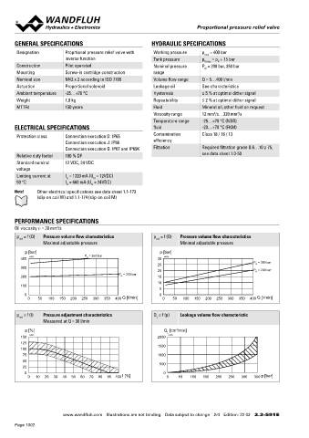
       PERFORMANCE SPECIFICATIONS                                                                                                  PARTS LIST                                           COMMISSIONING
                       2
       Oil viscosity u = 30 mm /s                                                                                                                                                       When commissioning, the valve must be vented under pressure as
                                                                                                                                     Position Article  Description
       p  = f (Q)  Pressure volume flow characteristics     p  = f (Q)  Pressure volume flow characteristics                                                                            follows (see detail X in Dimensions):
        red                                                  red                                                                         10 206.2…  W.S37 / 19 x 50
                  Maximal adjustable pressure                         Minimal adjustable pressure
                                                                                                                                            260.5…  M.S35 / 19 x 50                        Loosen lock nut
           p [bar]                                             p [bar]                                                                   12 154.2700  Knurled nut                        ◆  Remove screw (E)
         400  K4272               P N  = 350 bar              30  K4273                                                                  17 160.2187  O-ring ID 18,72 x 2,62 (NBR)       ◆  Push the non-return valve (with pin or hex key < 1,3 mm)
                                                              25                                   P N  = 350 bar                                                                        ◆
         300                                                                                                                             18 160.2170  O-ring ID 17,17 x 1,78 (NBR)       ◆  Screw-in the screw (E)
                                                              20                                   P N  = 200 bar
                                               P N  = 200 bar                                                                                                                            ◆  Adjust the required pressure and tighten the lock nut
         200                                                  15                                                                         50 160.2377  O-ring ID 37,77 x 2,62 (NBR)
                                                              10                                                                            160.6379  O-ring ID 37,77 x 2,62 (FKM)
         100
                                                              5                                                                          60 160.2314  O-ring ID 31,42 x 2,62 (NBR)               Therewith oil flows out with the corresponding
           0                                                  0                                                                             160.6315  O-ring ID 31,42 x 2,62 (FKM)      Attention!
            0   50  100  150  200  250  300  350  400  Q [l/min]  0  50  100  150  200  250  300  350  400  Q [l/min]                                                                            pressure! Cover with a cloth.
                                                                                                                                         70 049.8364  Backup ring PTSM rd 29,1 x 33,6 x 1 ,4
       p  = f (I)  Pressure adjustment characteristics      Q  = f (p)  Leakage volume flow characteristic
        red                                                  L
                  Measured at Q = 30 l/min                                                                                         STANDARDS                                            INSTALLATION NOTES
           p [%]                                                Q  [cm /min]                                                        Cartridge cavity    ISO 7789                         Mounting type      Screw-in cartridge M42 x 2
                                                                     3
                                                                 L
         150  K4273                                           2000  K4275                                                           Solenoids           DIN VDE 0580                     Mounting position  Any, preferably horizontal
         125
                                                              1500                                                                  Connection execution D  EN 175301 – 803              Tightening torque  M  = 280 Nm Screw-in cartridge
         100                                                                                                                                                                                                M  = 5 Nm knurled nut
                                                                                                                                                                                                             D
          75                                                  1000                                                                  Protection class    EN 60 529                                            D
          50                                                                                                                        Contamination efficiency  ISO 4406
          25                                                  500
           0                                                    0
            0  10  20  30  40  50  60  70  80  90  100  I [%]    0    50  100  150  200  250  300  350  p [bar]


                         www.wandfluh.com  Illustrations are not binding  Data subject to change  2/4  Edition: 22 02  2.3-591 E                      www.wandfluh.com  Illustrations are not binding  Data subject to change  3/4  Edition: 22 02  2.3-591 E
       Page 1002
   997   998   999   1000   1001   1002   1003   1004   1005   1006   1007