
Page 958 - Softbound_Edition_19_en
P. 958
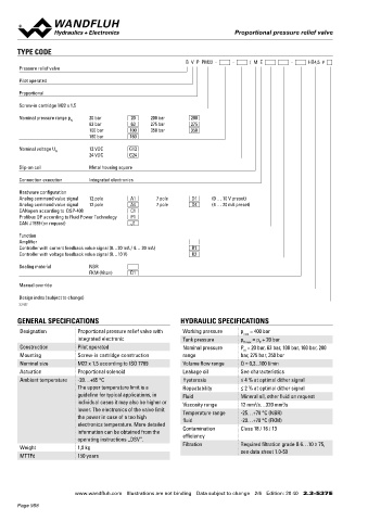
Proportional pressure relief valve
Proportional pressure relief valve Proportional pressure relief valve
TYPE CODE ELECTRICAL CONNECTION
B V P PM22 - - / M E - HB4,5 # X1 Analog interface (Main) X1 Fieldbus interface (Main)
Pressure relief valve
Device receptacle M23, 12 pole male Device receptacle M12, 4 pole male
Pilot operated 1 = Supply voltage + 2 1 1 = Supply voltage +
8 9 1 2 = Supply voltage 0 VDC 3 4 2 = Reserved for extentions
Proportional 7 12 10 2 3 = Stabilised output voltage 3 = Supply voltage 0 VDC
6 11 3
5 4 4 = Command value signal voltage + 4 = Chassis
Screw-in cartridge M22 x 1,5
5 = Command value signal voltage -
Nominal pressure range p 20 bar 20 200 bar 200 6 = Command value signal current +
N
63 bar 63 275 bar 275 7 = Command value signal current -
100 bar 100 350 bar 350 8 = Reserved for extentions
160 bar 160 9 = Reserved for extentions X2 Parameterisation interface
10 = Enable signal (Digital input) USB, Mini B Under the screw plug of the housing
Nominal voltage U 12 VDC G12
N 11 = Error signal (Digital output) cover
24 VDC G24
12 = Chassis Factory set
Slip-on coil Metal housing square Command value signal voltage (PIN 4/5) resp. current (PIN 6/7) are
selected with parameterisation and diagnostics software PASO.
Connection execution Integrated electronics
Hardware configuration
Analog command value signal 12 pole A1 7 pole D1 (0 … 10 V preset) X1 Analog interface (Main) X3 Profibus interface according to IEC
Analog command value signal 12 pole A4 7 pole D4 (4 … 20 mA preset) Connector DIN EN 175201 - 804 947-5-2
CANopen according to DSP-408 C1
Profibus DP according to Fluid Power Technology P1 Device receptacle 7 pole male Device receptacle M12, 5 pole female B-coded
CAN J1939 (on request) J1 A = Supply voltage + 2 3 1 = VP
A 5
F B B = Supply voltage 0 VDC 1 4 2 = RxD / TxD - N
Function G C = Not connected 3 = DGND
Amplifier E D C D = Command value signal + 4 = RxD / TxD - P
Controller with current feedback value signal (0…20 mA / 4… 20 mA) R1
Controller with voltage feedback value signal (0…10 V) R2 E = Command value signal - 5 = Shield
F = Not connected
Sealing material NBR G = Chassis
FKM (Viton) D1
Command value signal: current (D4) or voltage (D2) to specify
Manual override when placing the order
Design index (subject to change)
2.3-537 X3 CANopen interface according to DRP X4 (controller only) Feedback value interface (sensor)
303-1 Device receptacle M12, 5 pole female
GENERAL SPECIFICATIONS HYDRAULIC SPECIFICATIONS Device receptacle M12, 5 pole male 2 3 1 = Supply voltage (output) +
5
Designation Proportional pressure relief valve with Working pressure p = 400 bar 2 1 1 = Not connected 1 4 2 = Feedback value signal +
max
5
integrated electronic Tank pressure p = p + 20 bar 3 4 2 = Not connected 3 = Supply voltage 0 VDC
T max
P
Construction Pilot operated Nominal pressure P = 20 bar, 63 bar, 100 bar, 160 bar, 200 3 = CAN Gnd 4 = Not connected
4 = CAN High
5 = Stabilised output voltage
N
Mounting Screw-in cartridge construction range bar, 275 bar, 350 bar 5 = CAN Low
Nominal size M22 x 1,5 according to ISO 7789 Volume flow range Q = 0,3...100 l/min Feedback value signal: current (R1) or voltage (R2) to specify
when placing the order
Actuation Proportional solenoid Leakage oil See characteristics
Ambient temperature -20…+65 °C Hysteresis ≤ 4 % at optimal dither signal
The upper temperature limit is a Repeatability ≤ 2 % at optimal dither signal Note! The mating connector is not included in the delivery
guideline for typical applications, in Fluid Mineral oil, other fluid on request
individual cases it may also be higher or Viscosity range 12 mm /s…320 mm /s
2
2
lower. The electronics of the valve limit Temperature range -25…+70 °C (NBR)
the power in case of a too high fluid -20…+70 °C (FKM)
electronics temperature. More detailed
information can be obtained from the Contamination Class 18 / 16 / 13
operating instructions „DSV”. efficiency
Weight 1,0 kg Filtration Required filtration grade ß 6…10 ≥ 75,
see data sheet 1.0-50
MTTFd 150 years
www.wandfluh.com Illustrations are not binding Data subject to change 2/6 Edition: 20 40 2.3-537 E www.wandfluh.com Illustrations are not binding Data subject to change 3/6 Edition: 20 40 2.3-537 E
Page 958