Page 960 - Softbound_Edition_19_en
P. 960

Proportional pressure relief valve
                                                                             Proportional pressure relief valve                                                                                           Proportional pressure relief valve


       PERFORMANCE SPECIFICATIONS                                                                                                  DIMENSIONS
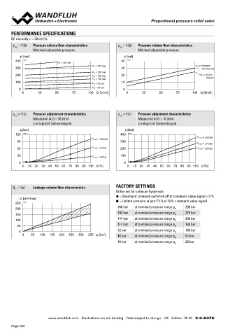
       Oil viscosity u = 30 mm /s                                                                                                  With analog interface, 12 pole connector             With analog interface, 7 pole connector
                       2
       p  = f (Q)  Pressure volume flow characteristics     p  = f (Q)  Pressure volume flow characteristics                         Amplifier and controller                           Amplifier and controller
                                                             red
        red
                  Maximal adjustable pressure                         Minimal adjustable pressure                                                   25,30      20,21    40                               X2
           p [bar]                                             p [bar]                                                                                         X2
         400  K0220                                           40  K0221
                              P N  = 350 bar                                                                                                             X1                                        X1
                                               P N  = 275 bar                                      P N  = 160/200/
         300                                                  30                                            275/350 bar
                                               P N  = 200 bar                                                                                                             s30
         200                                   P N  = 160 bar  20                                     P N  = 20/63/                                      X4                               118.4    X4
                                               P N  = 100 bar                                                 100 bar                 100.4
         100                                   P N  = 63 bar  10                                                                                                          M22x1.5  (2)
                                                                                                                                                 15
           0                                   P N  = 20 bar   0                                                                        35    MD=5.5Nm                           (1)        35
            0       25       50      75      100 Q [l/min]      0       25       50      75       100 Q [l/min]

                                                                                                                                                 12     17         18     50  70  60
                                                                                                                                               MD=5Nm
                                                                                                                                                               78.4
                                                                                                                                                              95
       p  = f (n)  Pressure adjustment characteristics      p  = f (n)  Pressure adjustment characteristics                                              135                38.5
                                                             red
        red
                  Measured at Q = 10 l/min                            Measured at Q = 10 l/min                                                                174
                  s entspricht Sollwertsignal                         s entspricht Sollwertsignal                                  X4 (controller only)
           p [bar]                                              p [bar]                                                            With fieldbus interface                              With fieldbus interface
         120  K4100_1                                        400  K4100                                                            Amplifier                                            Controller
                                                                                                    P N red = 350 bar
                                               P N red = 100 bar
          90                                                 300                                                                                                                                           X2
                                                                                                    P N red = 275 bar
          60                                   P N red = 63 bar  200                                P N red = 200 bar                                     X2                                         X1
          30                                   P N red = 20 bar  100                                                                               X1                                                X3
           0                                                  0  
            0   10  20  30  40 50 60 70 80 90  100 s [%]         0   10  20  30  40 50 60 70 80 90  100 s [%]                         100.4        X3                                     118.4      X4


                                                                                                                                       35                                                   35
       Q  = f (p)  Leakage volume flow characteristic      FACTORY SETTINGS
         L
                                                           Dither set for optimum hysteresis
                                                           ● = Deadband: solenoid switched off at command value signal < 5 %
           Q [cm /min]
               3
         250  K0223                                        ■ = Limited pressure in port P (1) at 70 % command value signal
                                                            248 bar  at nominal pressure range p  350 bar
         200                                                                             N                                         HYDRAULIC CONNECTION                                 PARTS LIST
                                                            192 bar  at nominal pressure range p  275 bar
         150                                                                             N                                         Cavity drawing according to ISO 7789–22–02–0–98       Position Article  Description
         100                                                144 bar  at nominal pressure range p N  200 bar                                                                                   12 154.2700  Knurled nut
          50                                                114 bar  at nominal pressure range p N  160 bar                                              M22x1.5                              15 253.8000  Manual override HB4,5
           0                                                72 bar   at nominal pressure range p N  100 bar
            0    50  100  150  200  250  300  350 p [bar]   46 bar   at nominal pressure range p  63 bar                                                                                      17 160.2187  O-ring ID 18,72 x 2,62 (NBR)
                                                                                         N
                                                            16 bar   at nominal pressure range p  20 bar                                                          (2)                         18 160.2170  O-ring ID 17,17 x 1,78 (NBR)
                                                                                         N
                                                                                                                                                                                              20 223.1317  Dummy plug M16 x 1,5
                                                                                                                                                                                              21 160.6131  O-ring ID 13,00 x 1,5 (FKM)
                                                                                                                                                                  (1)
                                                                                                                                                                                              25 062.0102  Cover
                                                                                                                                                          (1)                                 30 072.0021  Gasket 33,2 x 59,9 x 2
                                                                                                                                                                                              40 208.0100  Socket head screw M4 x 10
                                                                                                                                   Note!    For detailed cavity drawing and cavity tools see data   50 160.2188  O-ring ID 18,77 x 1,78 (NBR)
                                                                                                                                            sheet 2.13-1003                                      160.6188  O-ring ID 18,77 x 1,78 (FKM)
                                                                                                                                                                                              60 160.2140  O-ring ID 14,00 x 1,78 (NBR)
                                                                                                                                                                                                 160.6141  O-ring ID 14,00 x 1,78 (FKM)
                                                                                                                                                                                              70 049.3177  Back-up ring rd 14,6 x 17,5 x 1,4


                         www.wandfluh.com  Illustrations are not binding  Data subject to change  4/6  Edition: 20 40  2.3-537 E                      www.wandfluh.com  Illustrations are not binding  Data subject to change  5/6  Edition: 20 40  2.3-537 E
       Page 960
   955   956   957   958   959   960   961   962   963   964   965