Page 279 - Softbound_Edition_19_en
P. 279

Spool valve
                                                                                                       Spool valve


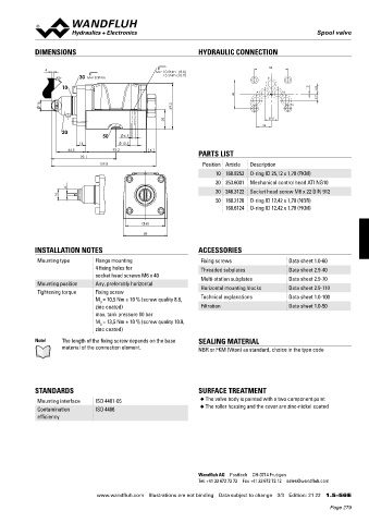
            DIMENSIONS                                           HYDRAULIC CONNECTION

                                                                                         54
                4                                  MD= 10.5Nm   (8.8)
                           30                         13.5Nm (10.9)
                    45°      MD= 8.9Nm                                                 P


                     10                                                                               1.5
                                                                                    A       B           16.8
                                                                              46
                                                                                                        9.7
              16                                         69.5                     T            To

                                                       29                               20.8
                                                                                      24
                     20
                                  50      6.5
                           14             10.5
                        44.5          93.2       14.1
                            99.1                                 PARTS LIST
                                  159.8                           Position Article  Description
                                                                       10 160.8252  O-ring ID 25,12 x 1,78 (FKM)
                                                                       20 253.6001  Mechanical control head ATI NG10
                       4.1                                             30 246.3122  Socket head screw M6 x 22 DIN 912
                     16
                                                                       50 160.2120  O-ring ID 12,42 x 1,78 (NBR)
                                                                          160.6124  O-ring ID 12,42 x 1,78 (FKM)

                                                 60
                                                68

            INSTALLATION NOTES                                   ACCESSORIES

             Mounting type      Flange mounting                   Fixing screws               Data sheet 1.0-60
                                4 fixing holes for                Threaded subplates          Data sheet 2.9-40
                                socket head screws M6 x 40        Multi-station subplates     Data sheet 2.9-70
             Mounting position  Any, preferably horizontal
             Tightening torque  Fixing screw                      Horizontal mounting blocks  Data sheet 2.9-110
                                M = 10,5 Nm ± 10 % (screw quality 8.8,   Technical explanations  Data sheet 1.0-100
                                 D
                                zinc coated)                      Filtration                  Data sheet 1.0-50
                                max. tank pressure 80 bar
                                M = 13,5 Nm ± 10 % (screw quality 10.9,
                                 D
                                zinc coated)
            Note!    The length of the fixing screw depends on the base   SEALING MATERIAL
                     material of the connection element.         NBR or FKM (Viton) as standard, choice in the type code


            STANDARDS                                            SURFACE TREATMENT
             Mounting interface  ISO 4401-05                      ◆  The valve body is painted with a two component paint
             Contamination      ISO 4406                          ◆  The roller housing and the cover are zinc-nickel coated
             efficiency


                                                                 Wandfluh AG  Postfach  CH-3714 Frutigen
                                                                 Tel. +41 33 672 72 72  Fax +41 33 672 72 12  sales@wandfluh.com

                                www.wandfluh.com  Illustrations are not binding  Data subject to change  3/3  Edition: 21 22  1.5-56 E
                                                                                                            Page 279
   274   275   276   277   278   279   280   281   282   283   284