
Page 139 - Softbound_Edition_19_en
P. 139
Solenoid operated spool valve
Solenoid operated spool valve
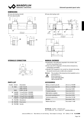
DIMENSIONS
4/3-way valve (spring centred) 4/2-way valve (spring reset)
4/2-way valve (impulse)
A B A
9.5
5.2 MD= 5.2Nm
6
77
37 38
V = 32
10
173 Economy 70 60 10 50
193 Medium
MD= 5Nm 40 Economy
18 50 Medium 57 8
HF1 HS1 123 Economy
43 44 133 Medium
30 30
80
90
A
77
35
N =
10
15 53
133
HYDRAULIC CONNECTION MANUAL OVERRIDE
◆ Integrated (–) Actuation pin integrated in the armature tube.
28 Actuation by pressing the pin
14 ◆ Push-button (HF1) Integrated in the knurled nut. Actuation by
pressing the push-button
P ◆ Spindle (HS1) Integrated in the knurled nut. Actuation by turning
the spindle (continuously variable valve actuation)
A B
14 27 Attention! The actuation of the manual override is possible up to a
T T0 tank pressure of:
40 bar Integrated (–)
40 bar Push-button (HF1)
100 bar Spindle (HS1)
PARTS LIST ACCESSORIES
Position Article Description Mating connector grey (A) Article no. 219.2001
10 206.2... V.E37 / 19 x 40 Mating connector black (B) Article no. 219.2002
V.E37 / 19 x 50 Mounting screws Data sheet 1.0-60
260.5... N.S35 / 19 x 50 Threaded subplates Data sheet 2.9-10
50 160.2052 O-ring ID 5,28 x 1,78 (NBR) Multi-station subplates Data sheet 2.9-50
160.6052 O-ring ID 5,28 x 1,78 (FKM)
Horizontal mounting blocks Data sheet 2.9-90
60 160.2187 O-ring ID 18,72 x 2,62 (NBR)
160.6187 O-ring ID 18,72 x 2,62 (FKM) Technical explanations Data sheet 1.0-100
70 154.2700 Knurled nut Filtration Data sheet 1.1-50
Relative duty factor Data sheet 1.1-430
80 253.7001 Push-button
90 253.7000 Spindle
Wandfluh AG Postfach CH-3714 Frutigen
Tel. +41 33 672 72 72 Fax +41 33 672 72 12 sales@wandfluh.com
www.wandfluh.com Illustrations are not binding Data subject to change 5/5 Edition: 21 40 1.2-33 E
Page 139