
Page 138 - Softbound_Edition_19_en
P. 138
Solenoid operated spool valve
Solenoid operated spool valve Solenoid operated spool valve
PERFORMANCE SPECIFICATIONS DIMENSIONS
Oil viscosity u = 30 mm /s 4/3-way valve (spring centred) 4/2-way valve (spring reset)
2
4/2-way valve (impulse)
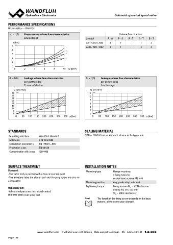
Δp = f (Q) Pressure drop volume flow characteristics Volume flow direction
Low Leakage Symbol P - A P - B P - T A - T B - T A B A
9.5
p [bar] AB1 / AB2 / AB3 1 1 - 1 2 5.2 MD= 5.2Nm
5 K1030 6
1 ADB / AD1 / DB2 1 1 - 4 3 77
4 2
3 3 37 32 38
2 4 V =
1 10
0 173 Economy 70 60 10 50
193 Medium
0 2 4 6 8 10 Q [l/min] MD= 5Nm 40 Economy
18 50 Medium 57 8
HF1 43 HS1 44 123 Economy
133 Medium
Q = f (Q) Leakage volume flow characteristics Q = f (Q) Leakage volume flow characteristics 30 30
L L 80
per control edge per control edge 90
Economy/Medium Low Leakage A
Q [cm /min] Q [cm /min]
3
3
40 K1031 12 K1032 77
35 10 35
30
25 8 N =
20 6
15 4
10 10
5 2 15 53
0 0 133
0 50 100 150 200 250 300 350 p [bar] 0 50 100 150 200 250 300 350 p [bar]
HYDRAULIC CONNECTION MANUAL OVERRIDE
◆ Integrated (–) Actuation pin integrated in the armature tube.
STANDARDS SEALING MATERIAL 28 Actuation by pressing the pin
Mounting interface Wandfluh standard NBR or FKM (Viton) as standard, choice in the type code 14 ◆ Push-button (HF1) Integrated in the knurled nut. Actuation by
pressing the push-button
Solenoids DIN VDE 0580 P Spindle (HS1) Integrated in the knurled nut. Actuation by turning
Connection execution D EN 175301 – 803 ◆ the spindle (continuously variable valve actuation)
A B
Protection class EN 60 529 14 27 Attention! The actuation of the manual override is possible up to a
Contamination efficiency ISO 4406 T T0 tank pressure of:
40 bar Integrated (–)
40 bar Push-button (HF1)
100 bar Spindle (HS1)
SURFACE TREATMENT INSTALLATION NOTES PARTS LIST ACCESSORIES
Standard: Mounting type Flange mounting
-The valve body is painted with a two component paint 3 fixing holes for Position Article Description Mating connector grey (A) Article no. 219.2001
-The armature tube, the slip-on coil and the plug screw are zinc-ni- socket head screws M5 x 40 10 206.2... V.E37 / 19 x 40 Mating connector black (B) Article no. 219.2002
ckel coated Mounting position Any, preferably horizontal V.E37 / 19 x 50 Mounting screws Data sheet 1.0-60
Tightening torque Fixing screws M = 5,2 Nm (screw 260.5... N.S35 / 19 x 50 Threaded subplates Data sheet 2.9-10
Optionally (K8): quality 8.8, zinc coated) 50 160.2052 O-ring ID 5,28 x 1,78 (NBR)
D
-All external parts are zinc-nickel coated M = 5 Nm knurled nut 160.6052 O-ring ID 5,28 x 1,78 (FKM) Multi-station subplates Data sheet 2.9-50
ISO 9227 (800 h) salt spray test D 60 160.2187 O-ring ID 18,72 x 2,62 (NBR) Horizontal mounting blocks Data sheet 2.9-90
Note! The length of the fixing screw depends on the base 160.6187 O-ring ID 18,72 x 2,62 (FKM) Technical explanations Data sheet 1.0-100
material of the connection element. Filtration Data sheet 1.1-50
70 154.2700 Knurled nut
Relative duty factor Data sheet 1.1-430
80 253.7001 Push-button
90 253.7000 Spindle
Wandfluh AG Postfach CH-3714 Frutigen
Tel. +41 33 672 72 72 Fax +41 33 672 72 12 sales@wandfluh.com
www.wandfluh.com Illustrations are not binding Data subject to change 4/5 Edition: 21 40 1.2-33 E www.wandfluh.com Illustrations are not binding Data subject to change 5/5 Edition: 21 40 1.2-33 E
Page 138