Page 1023 - Softbound_Edition_19_en
P. 1023

Proportional pressure reducing valve
                                                                               Proportional pressure reducing valve


            PERFORMANCE SPECIFICATIONS
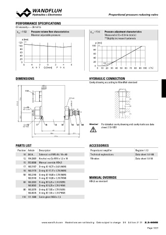
            Oil viscosity u = 30 mm /s
                             2
             p  = f (Q)  Pressure volume flow characteristics     p  = f (n)  Pressure adjustment characteristics
              red
                                                                   red
                       Maximal adjustable pressure                          Measured at Q = 0 l/min (static)
                 p [bar]                                                    **Slightly increased hysteresis
              120  K1154                                             p [bar]
              100                                                  100  K1153
               80                                                   80
               60                                                   60
               40
               20                                                   40
                0                                                   20
                  6    4     2     0     2    4     6                0     **
                        A     T  Q [l/min]  P   A                    0   10  20  30  40 50 60 70 80 90  100 l [%]

            DIMENSIONS                                           HYDRAULIC CONNECTION
                                                                 Cavity drawing according to Wandfluh standard

                                                                                       M16x1.5
                   110

                 70.8                                s30                                      (3)
               93.3                                 M16x1.5
                    15                                                                        (2)
                  MD=5.5Nm                           (3)  (2)
                                                          (1)
                                                                                              (1)
                 22.5                                                                   (1)

                    12     17    18     10   18     50  60  80   Attention!  For detailed cavity drawing and cavity tools see data
                 MD=9Nm                                                   sheet 2.13-1051
                                       60
                                      88.6            27.1
                                         122.6

            PARTS LIST                                           ACCESSORIES

              Position Article  Description                       Proportional amplifier          Register 1.13
                  10 263.6...  Solenoid coil MK.45 / 18 x 60      Technical explanations          Data sheet 1.0-100
                  12 154.2603  Knurled nut Ex M18 x 1,5 x 18      Filtration                      Data sheet 1.0-50
                  15 253.8000  Manual override HB4,5
                  17 160.2187  O-ring ID 18,72 x 2,62 (NBR)
                  18 160.2170  O-ring ID 17,17 x 1,78 (NBR)
                  50 160.2140  O-ring ID 14,00 x 1,78 (NBR)
                     160.8140  O-ring ID 14,00 x 1,78 (FKM)      MANUAL OVERRIDE
                  60 160.2093  O-ring ID 9,25 x 1,78 (NBR)       HB4,5 as standard
                     160.8092  O-ring ID 9,25 x 1,78 (FKM)
                  80 160.2076  O-ring ID 7,65 x 1,78 (NBR)
                     160.8076  O-ring ID 7,65 x 1,78 (FKM)
                 110 111.1080  Cable gland M20 x 1,5


                               www.wandfluh.com  Illustrations are not binding  Data subject to change  3/4  Edition: 21 21  2.3-608 E
                                                                                                           Page 1023
   1018   1019   1020   1021   1022   1023   1024   1025   1026   1027   1028