
Page 1018 - Softbound_Edition_19_en
P. 1018
Proportional pressure reducing valve
Proportional pressure reducing valve Proportional pressure reducing valve
TYPE CODE PERFORMANCE SPECIFICATIONS
2
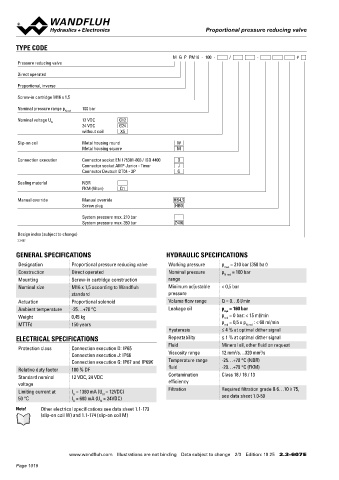
M G P PM16 - 100 - / - # Oil viscosity u = 30 mm /s
Pressure reducing valve p = f (Q) Pressure volume flow characteristics p = f (n) Pressure adjustment characteristics
red
red
Direct operated Maximal adjustable pressure Measured at Q = 0 l/min (static)
p [bar] **Slightly increased hysteresis
Proportional, inverse 120 K1154 p [bar]
100 100 K1153
Screw-in cartridge M16 x 1,5
80 80
Nominal pressure range p 100 bar 60 60
N red
40
Nominal voltage U 12 VDC G12 20 40
N
24 VDC G24 0 20
without coil X5 6 4 2 0 2 4 6 0 **
A T Q [l/min] P A 0 10 20 30 40 50 60 70 80 90 100 l [%]
Slip-on coil Metal housing round W
Metal housing square M
Connection execution Connector socket EN 175301-803 / ISO 4400 D
Connector socket AMP Junior - Timer J DIMENSIONS HYDRAULIC CONNECTION
Connector Deutsch DT04 - 2P G Cavity drawing according to Wandfluh standard
Sealing material NBR
FKM (Viton) D1 s30 M16x1.5
Manual override Manual override HB4,5 15
Screw plug HB0 MD=5.5Nm M16x1.5 (3)
76.8
System pressure max. 210 bar 37.1 (3) (2)
System pressure max. 350 bar Z406 (1) (2)
W =
Design index (subject to change)
(1)
2.3-607
12 17 10 18 50 60 80 (1)
MD=5Nm
GENERAL SPECIFICATIONS HYDRAULIC SPECIFICATIONS 78.3 27.1 Attention! For detailed cavity drawing and cavity tools see data
Designation Proportional pressure reducing valve Working pressure p = 210 bar (350 bar) 111.6 sheet 2.13-1051
max
Construction Direct operated Nominal pressure p N red = 100 bar HB0
Mounting Screw-in cartridge construction range 15
Nominal size M16 x 1,5 according to Wandfluh Minimum adjustable < 0,5 bar MD= 9.5Nm PARTS LIST
standard pressure Position Article Description
Actuation Proportional solenoid Volume flow range Q = 0…6 l/min 74.8 10 206.2… W.S37 / 19 x 50
Ambient temperature -25…+70 °C Leakage oil p = 160 bar 35 260.5… M.S35 / 19 x 50
sys
Weight 0,45 kg p = 0 bar: < 15 ml/min M = 12 154.2700 Knurled nut
red
MTTFd 150 years p = 0,5 x p N red : < 60 ml/min
red
Hysteresis ≤ 4 % at optimal dither signal 10 15 253.8000 HB4,5 manual override
ELECTRICAL SPECIFICATIONS Repeatability ≤ 1 % at optimal dither signal 239.2033 HB0 Screw plug
Fluid Mineral oil, other fluid on request 17 160.2187 O-ring ID 18,72 x 2,62 (NBR)
Protection class Connection execution D: IP65 2 2 18 160.2170 O-ring ID 17,17 x 1,78 (NBR)
Connection execution J: IP66 Viscosity range 12 mm /s…320 mm /s
Connection execution G: IP67 and IP69K Temperature range -25…+70 °C (NBR) 50 160.2140 O-ring ID 14,00 x 1,78 (NBR)
Relative duty factor 100 % DF fluid -20…+70 °C (FKM) 160.8140 O-ring ID 14,00 x 1,78 (FKM)
Standard nominal 12 VDC, 24 VDC Contamination Class 18 / 16 / 13 60 160.2093 O-ring ID 9,25 x 1,78 (NBR)
voltage efficiency 160.8092 O-ring ID 9,25 x 1,78 (FKM)
Limiting current at I = 1360 mA (U = 12VDC) Filtration Required filtration grade ß 6…10 ≥ 75, 80 160.2076 O-ring ID 7,65 x 1,78 (NBR)
G
N
50 °C I = 680 mA (U = 24VDC) see data sheet 1.0-50 160.8076 O-ring ID 7,65 x 1,78 (FKM)
G N
Note! Other electrical specifications see data sheet 1.1-173
(slip-on coil W) and 1.1-174 (slip-on coil M)
Wandfluh AG Postfach CH-3714 Frutigen
Tel. +41 33 672 72 72 Fax +41 33 672 72 12 sales@wandfluh.com
www.wandfluh.com Illustrations are not binding Data subject to change 2/3 Edition: 19 25 2.3-607 E www.wandfluh.com Illustrations are not binding Data subject to change 3/3 Edition: 19 25 2.3-607 E
Page 1018