
Page 985 - Softbound_Edition_19_en
P. 985
Proportional
Proportional pressure relief valve
pressure relief valves
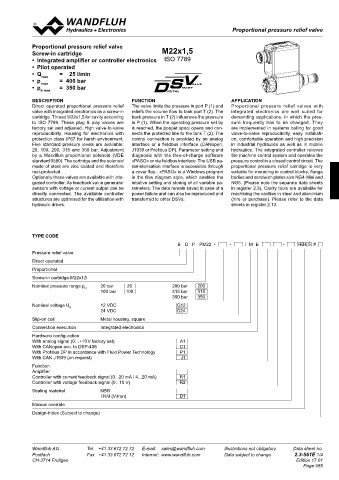
Proportional pressure relief valve
Screw-in cartridge M22x1,5
• Integrated amplifier or controller electronics ISO 7789
• Pilot operated
• Q max = 25 l/min
• p max = 400 bar
• p = 350 bar
N max
DESCRIPTION FUNCTION APPLICATION
Direct operated proportional pressure relief The valve limits the pressure in port P (1) and Proportional pressure relief valves with
valve with integrated electronics as a screw-in reliefs the volume flow to tank port T (2). The integrated electronics are well suited for
cartridge. Thread M22x1,5 for cavity according back pressure in T (2) influences the pressure demanding applications, in which the pres-
to ISO 7789. These plug & play valves are in P (1). When the operating pressure set by sure frequently has to be changed. They
factory set and adjusted. High valve-to-valve is reached, the poppet spool opens and con- are implemented in systems calling for good
reproducibility. Housing for electronics with nects the protected line to the tank T (2). The valve-to-valve reproducibility, easy installati-
protection class IP67 for harsh environment. control connection is provided by an analog on, comfortable operation and high precision
Five standard pressure levels are available: interface or a fieldbus interface (CANopen, in industrial hydraulics as well as in mobile
20, 100, 200, 315 and 350 bar. Adjustment J1939 or Profibus DP). Parameter setting and hydraulics. The integrated controller relieves
by a Wandfluh proportional solenoid (VDE diagnosis with the free-of-charge software the machine control system and operates the
standard 0580). The cartridge and the solenoid «PASO» or via fieldbus interface. The USB pa- pressure control in a closed control circuit. The
made of steel are zinc coated and therefore rameterisation interface is accessible through proportional pressure relief catridge is very
rust-protected. a cover flap.. «PASO» is a Windows program suitable for mounting in control blocks, flange
Optionally these valves are available with inte- in the flow diagram style, which enables the bodies and sandwich plates size NG4-Mini and
grated controller. As feedback value generator intuitive setting and storing of all variable pa- NG6. (Please note the separate data sheets
sensors with voltage or current output can be rameters. The data remain saved in case of a in register 2.3). Cavity tools are available for
directly connected. The available controller power failure and can also be reproduced and machining the cavities in steel and aluminium
structures are optimised for the utilisation with transferred to other DSVs. (hire or purchase). Please refer to the data
hydraulic drives. sheets in register 2.13.
TYPE CODE
B D P PM22 - - / M E - HB4,5 #
Pressure relief valve
Direct operated
Proportional
Screw-in cartridge M22x1,5
Nominal pressure range p 20 bar 20 200 bar 200
N
100 bar 100 315 bar 315
350 bar 350
Nominal voltage U 12 VDC G12
N
24 VDC G24
Slip-on coil Metal housing, square
Connection execution Integrated electronics
Hardware configuration
With analog signal (0…+10 V factory set) A1
With CANopen acc. to DSP-408 C1
With Profibus DP in accordance with Fluid Power Technology P1
With CAN J1939 (on request) J1
Function
Amplifier
Controller with current feedback signal (0...20 mA / 4...20 mA) R1
Controller with voltage feedback signal (0...10 V) R2
Sealing material NBR
FKM (Vitron) D1
Manual override
Design-Index (Subject to change)
Wandfluh AG Tel. +41 33 672 72 72 E-mail: sales@wandfluh.com Illustrations not obligatory Data sheet no.
Postfach Fax +41 33 672 72 12 Internet: www.wandfluh.com Data subject to change 2.3-561E 1/4
CH-3714 Frutigen Edition 17 01
Page 985