Page 982 - Softbound_Edition_19_en
P. 982

Proportional pressure relief valve
                                                                             Proportional pressure relief valve                                                                                           Proportional pressure relief valve


       PERFORMANCE SPECIFICATIONS                                                                                                  DIMENSIONS
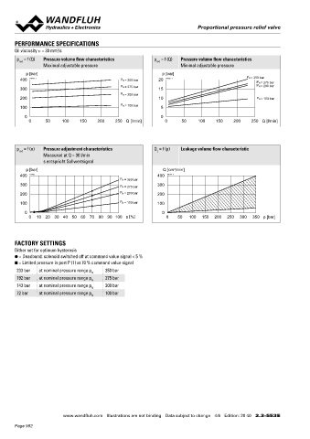
       Oil viscosity u = 30 mm /s                                                                                                  With analog interface, 12 pole connector             With analog interface, 7 pole connector
                       2
                                                                                                                                   Amplifier and controller                             Amplifier and controller
       p  = f (Q)  Pressure volume flow characteristics     p  = f (Q)  Pressure volume flow characteristics
                                                             red
        red
                  Maximal adjustable pressure                         Minimal adjustable pressure                                                 25, 30  20,21     40                                  X2
           p [bar]                                             p [bar]                                                                                       X2
         400  K0731_1                          P N = 350 bar  20  K0732_1                       P N = 350 bar                                                                                     X1
                                                                                                    P N = 275 bar                                      X1
         300                                   P N = 275 bar  15                                    P N = 200 bar                                                         s32
                                               P N = 200 bar                                                                                                                              120.9
         200                                                  10                                    P N = 100 bar                     102.9     15     X4                M33x2                    X4
                                               P N = 100 bar                                                                                 MD=5.5Nm                        (2)
         100                                                   5
                                                                                                                                       35                                         (1)      35
           0                                                   0
            0      50    100    150   200    250 Q [l/min]      0      50    100    150    200    250 Q [l/min]
                                                                                                                                                12     17       18      50    70   60
                                                                                                                                             MD=5Nm
                                                                                                                                                              86.1
                                                                                                                                                            102.7
                                                                                                                                                        143.1               51.8
       p  = f (n)  Pressure adjustment characteristics      Q  = f (p)  Leakage volume flow characteristic                                                   194.9
                                                             L
        red
                  Measured at Q = 30 l/min                                                                                         X4 (controller only)
                  s entspricht Sollwertsignal
           p [bar]                                              Q [cm /min]                                                        With fieldbus interface                              With fieldbus interface
                                                                    3
         400  K4102                                          400  K0734_1                                                          Amplifier                                            Controller
                                               P N = 350 bar
         300                                   P N = 275 bar  300                                                                                                                                        X2
                                                                                                                                                                                                   X1
         200                                   P N = 200 bar  200                                                                                       X2
                                                                                                                                                  X1
         100                                   P N = 100 bar  100                                                                                                                                  X3
           0                                                  0                                                                                  X3                                      120.9
            0   10  20  30  40 50 60 70 80 90  100 s [%]         0   50   100  150  200  250  300  350 p [bar]                        102.9                                                        X4

                                                                                                                                       35                                                   35

       FACTORY SETTINGS
       Dither set for optimum hysteresis
       ● = Deadband: solenoid switched off at command value signal < 5 %
       ■ = Limited pressure in port P (1) at 70 % command value signal
       233 bar  at nominal pressure range p  350 bar
                                    N
       192 bar  at nominal pressure range p  275 bar
                                    N                                                                                              HYDRAULIC CONNECTION                                 PARTS LIST
       143 bar  at nominal pressure range p  200 bar
                                    N                                                                                              Cavity drawing according to ISO 7789–33–02–0–98       Position Article  Description
       72 bar   at nominal pressure range p  100 bar
                                    N                                                                                                                                                         12 154.2700  Knurled nut
                                                                                                                                                         M33 x 2
                                                                                                                                                                                              15 253.8000  Manual override HB4,5
                                                                                                                                                                                              17 160.2187  O-ring ID 18,72 x 2,62 (NBR)
                                                                                                                                                                                              18 160.2170  O-ring ID 17,17 x 1,78 (NBR)
                                                                                                                                                                 (2)
                                                                                                                                                                                              20 223.1317  Dummy plug M16 x 1,5
                                                                                                                                                                                              21 160.6131  O-ring ID 13,00 x 1,5 (FKM)
                                                                                                                                                                                              25 062.0102  Cover
                                                                                                                                                                 (1)
                                                                                                                                                            (1)                               30 072.0021  Gasket 33,2 x 59,9 x 2
                                                                                                                                                                                              40 208.0100  Socket head screw M4 x 10
                                                                                                                                   Note!    For detailed cavity drawing and cavity tools see data   50 160.2298  O-ring ID 29,82 x 2,62 (NBR)
                                                                                                                                            sheet 2.13-1041                                      160.6296  O-ring ID 29,82 x 2,62 (FMK)
                                                                                                                                                                                              60 160.2219  O-ring ID 21,89 x 2,62 (NBR)
                                                                                                                                                                                                 160.6216  O-ring ID 21,89 x 2,62 (FKM)
                                                                                                                                                                                              70 049.3277  Backup ring rd 22,5 x 27 x 1,4


                         www.wandfluh.com  Illustrations are not binding  Data subject to change  4/6  Edition: 20 40  2.3-553 E                      www.wandfluh.com  Illustrations are not binding  Data subject to change  5/6  Edition: 20 40  2.3-553 E
       Page 982
   977   978   979   980   981   982   983   984   985   986   987