
Page 923 - Softbound_Edition_19_en
P. 923
Ø 9,5
Ø 5,5 ) s19
6
(
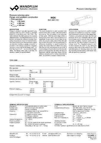
Pressure reducing valve
Pressure reducing valves Pressure reducing valves
6
s
38
32
2
CHARACTERISTICS oil viscosity υ = 30 mm /s Pressure reducing valve
p = f (Q) Pressure volume flow characteristics p = f (Q) Pressure volume flow characteristics Flange- and sandwich construction
red
red
10
54
(Maximal adjustable pressure) 68,8 37 (Minimal adjustable pressure) NG6
173,8 100 ∗ Consumption resistance dependent on system • Pilot operated ISO 4401-03
p [bar] p [bar] P N red = 200 bar P N red = 160 bar • Q max = 80 l/min
K0165 25 K0164 • p = 400 bar
200 Ø 5,5 P N red = 200 bar P N red = 80 bar • p max = 350 bar
160 20 P N red = 40 bar N red max
120 P N red = 160 bar 15 DESCRIPTION FUNCTION APPLICATION
80 P N red = 80 bar 10 Flange or sandwich type pilot operated 3-way The spool, located in the pilot operated main Pressure reducing valves are used for keeping
40 P N red = 40 bar 5 pressure reducing valve. Screw-in cartridge section of the valve, is held in the reset position the pressure constant in a consumer, irrespec-
0 ∗ M22x1,5 in according with ISO 7789. The by a spring. The connection to the consumer tive of pressure fluctuations on the supply side.
20 16 12 8 4 0 4 8 12 16 20 0 20 16 12 8 4 0 4 8 12 16 20 valve reduces the inlet pressure to a preset is fully open. With the pilot stage which is If several consumers are used, the reduced
A T Q [l/min] P A A T Q [l/min] P A output pressure. The integrated pressure relief designed as relief valve, reduced pressure is pressure can be set individually with the aid if
one pressure control valve for each consumer.
function prevents the reduced pressure from
adjustable. It opens when the set value is rea-
70 50 90 60 40 110 being exceeded as a result of external forces. ched. As a result, a pilot volume flows through Generally speaking, pressure control valves
p = f (n) Pressure adjustment characteristics ∆p = f (Q) Pressure loss/flow characteristics Two types of setting and three pressure stages the nozzle in the spool. The resultant pressure are used for reducing a hydraulic pressure to
red
[at Q = 0 l/min (static)] over non-return valve
28 are available. A pressure gauge connection is difference displaces the spool towards the a lower level. The integrated pressure relief
p [bar] 14 p [bar] provided in the reduced connection. A bypass spring. The volume flow is throttled in the valve function obviates the need for any additional
200 K0124 P N red = 200 bar 40 K0123 non-return valve plate for the flange valve – for inlet and the reduced pressure is controlled. If pressure relief valve in the reduced pipe. Pilot
free flow from A to P – can be ordered sepa- forces acting on the actuator allow the reduced operated pressure reducing valves also keep
150 P P N red = 160 bar 30 rately. The flange valve body is painted, the pressure to exceed the set value, the spool is the reduced pressure stable, even under very
A B sandwich plates are phosphatised. displaced until the valve inlet closes and the difficult operating conditions.
T To 14 27 20
100 P N red = 80 bar reduced pressure port is being connected to
tank. The pressure increase is then limited.
10
50 P N red = 40 bar
0
0 0 5 10 15 20 Q [l/min] TYPE CODE
0 1 2 3 4 5 6 7 8 9 n [-] M V A06 - - #
TYPES / DIMENSIONS
Pressure reducing valve
BDRVdN4
Flange Pilot operated
BDRVdN4 Ø 9,5 Type of adjustment Kay S
Ø 5,5 ) s19
6 Control knob D
(
Flange design F
6
s Sandwich design S
38
32 International standard interface ISO, NG6
A P T B
Type list / function Flange design Sandwich design
10 54 68,8 37 P → A P/A in P P
Sandwich 173,8 in A A
BDRVd4 BDRVdA4 BDRVdB4 100 in B B
BDRVd4
A P red T B A P T B A P T B BDRVdA4 Ø 5,5 Pressure range p N red 63 bar 63
160
160 bar
350 bar 350
Design-Index (Subject to change)
A P T B A red P T B A P T B red
GENERAL SPECIFICATIONS HYDRAULIC SPECIFICATIONS
70 50 90 60 40 110 Description Pilot operated pressure control valve Fluid Mineral oil, other fluid on request
PARTS LIST Nominal size NG6 according to ISO 4401-03 Contamination efficiency ISO 4406:1999, class 18/16/13
28 Construction Flange or sandwich (Required filtration grade ß6…10≥75)
Position Article Description 14 Mounting 4 mounting holes for zyl. screws M5 or Viscosity range refer to data sheet 1.0-50/2
12 mm /s…320 mm /s
double ended screws M5
2
2
40 153.1601 Hexagonal nut 0,5D M12 Spindle not secured against Connection Threaded connection plates Fluid temperature -20…+70 °C
= 400 bar
Peak pressure
Multi-flange subplates
p
50 246.1113 Zyl. screw M4 x 12 DIN912 A P B unscrewing Longitudinal stacking system Red. nominal pressure p max = 63 bar, p = 160 bar
60 246.1141 Zyl. screw M4 x 40 DIN912 T To 14 27 For sandwich red. pressure Ambient temperature -20…+50 °C p N red = 350 bar N red
N red
70 238.1405 Plug VSTI G1/8"-ED in B the adjusting parts are Mounting position any Opening pressure p = 2 bar
ö
90 160.2052 O-Ring ID 5,28 x 1,78 on A-side Fastening torque M = 5,5 Nm (qual.8.8) for fastening screws to non-return valve Q = 0…80 l/min
D
M = 50 Nm for screw-in cartridge
Volume flow
D
100 114.1202 Knob ACCESSORIES Weight Depending on the type 1,57…1,92 kg For futher hydraulic specifications see data sheet 2.2-530.
Threaded connection plates and Multi-flange subplates Register 2.9
110 154.7100 Cap nut Bypass non-return valve BDRVP4
Technical explanation see data sheet 1.0-100
Wandfluh AG Tel. +41 33 672 72 72 E-mail: sales@wandfluh.com Illustrations not obligatory Data sheet no. Wandfluh AG Tel. +41 33 672 72 72 E-mail: sales@wandfluh.com Illustrations not obligatory Data sheet no.
Postfach Fax +41 33 672 72 12 Internet: www.wandfluh.com Data subject to change 2.2-630E 2/2 Postfach Fax +41 33 672 72 12 Internet: www.wandfluh.com Data subject to change 2.2-640E 1/2
CH-3714 Frutigen Edition 21 30 CH-3714 Frutigen Edition 10 33
Page 923
A P T B
A P red T B A P T B A P T B
A P T B A red P T B A P T B red