
Page 865 - Softbound_Edition_19_en
P. 865
20
30
41
15
30
41
30
20
22
22
A
B
45
A
B
45
A
B
G1/4"
45
G1/4"
12
40
68
12
36
52
52
104
68
40
12 22 40 5,5 Æ 5,5 Æ 5,5 10 18 18 18 G1/4" 36 P P P T T T 104 68 10 ∗ 17,5 17,5 17,5 22,5 22,5 22,5 20
36
52 104
T
T
A B
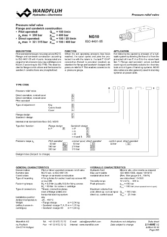
Pressure relief valve
A B Pressure relief valves Pressure relief valves
P ∗
P
REMARK! SCREW-IN CARTRIDGES INSTALLED Pressure relief valve
Detailed performance data and additional hydraulic The following screw-in cartridges are used in either the flange body or Flange and sandwich construction
19
specifications may by drawn from the data sheets of the 21,5 the sandwich body:
21,5
19
corresponding installed pressure relief cartridge. 17,8 • Pilot operated: Q max = 100 l/min
21,5 17,8 19 Designation Data sheet no. p max = 350 bar p = 400 bar NG10
Type
N
T 17,8 Pressure relief valve • Direct operated: Q max = 100 / 25 l/min
BV.PM22
T max
CAUTION! A B • pilot operated 2.1-530 p max = 32 / 315 bar p = 100 / 400 bar ISO 4401-05
45
31
B
The performace data especially the „pressure-flow-cha- A T BA.PM22 21 21 32,5 32,5 Pressure relief valve N max
45
31
22,5
22,5
racteristic„ on the data sheets of the screw-in catridges A P B 21 • direct operated 2.1-540
45
31
refere to the screw-in cartridges only. The additional press- P BK.PM22 32,5 Pressure relief valvee
22,5
ure drop of the flange body respectivly sandwich body must A=102 P∗ A=102 • direct operated 2.1-542 DESCRIPTION FUNCTION APPLICATION
∗
be taken into consideration. B=102 Pilot operated pressure reducing valves NG10. When the set operating pressure has been For relieving the operating pressure of a hyd-
B=102
A=102 Flange and sandwich construction according reached, the spool opens and joins the pro- raulic system by diverting the flow of oil from the
AB=140
AB=140 B=102 to ISO 4401-05 with 4 ports. Incorporated are tected line with the return to the tank T. G1/4" protected oil lines P, A or B to the return / tank
AB=140 proportional pressure reducing cartridges size connection thread is provided (sealed) as line T. Flange and sandwich valves (vertical
TYPES / DIMENSIONS M22x1,5 according to ISO 7789. The steel bo- standard for flange and sandwich designs with stacking) are particularly suitable for: machine
Flange construction Flange construction dies for flange constructions and the bodies for pressure relief in P. This enables connection to tools and all types of handling systems. NG10
B..FA06-P sandwich constructions are phosphatized. a pressure gauge. size valves are also generally used in stacking
30 10 20 systems on power units.
15 30 41 10 20
22 30 41 20
22
22 T TYPE CODE
A T B ∗
A P T B A B 45
5,5 T 45 B A 10 - - #
Æ 5,5 18 18 G1/4" A P B 17,5 17,5 22,5 22,5 Pressure relief valve
G1/4"
Æ 5,5 P 45 Direct operation, conical spool A
12 40 18 G1/4" 36 P 68 17,5 22,5
12 40 36 68 Direct operation, conical spool K
Sandwich construction 52 40 104 68 Pilot operated V
52
104
B..SA06-P 12 36
52 Sandwich construction in P Type of adjustment Key S
104
Control knob D
Cover A
T
T
A B Flange design F
A B Sandwich design S
A P T B P ∗
P International standard interface ISO, NG10
B..SA06-A
Type list / function Flange design Sandwich design
Sandwich construction in A, B or AB in P P in P P
21,5 19 in A A
21,5 19
17,8 in B B
21,5 17,8 19 in A and B AB
T 17,8
A P T B T
A B Pressure range p Pilot operated conical spool, direct operated control spool, direct operated
N
B..SA06-B B..SA06-AB 31 A T B 21 32,5 45 63 bar 63 63 bar 63 32 bar 32
31 21 32,5 22,5 45 160 bar 160 210 bar 210
A P B 22,5
31 P 21 32,5 45 350 bar 350 315 bar 315
∗ A=102 ∗ 22,5
A=102 P
B=102 Design-Index (Subject to change)
A=102 B=102
AB=140
AB=140 B=102
A P T B A P T B
AB=140
GENERAL CHARACTERISTICS HYDRAULIC CHARACTERISTICS
PARTS LIST Denomination Pilot or direct operated pressure relief valve Hydraulic fluid Mineral oils, other media on request
Nominal size NG10 acc. to ISO 4401-05 Max. permissible ISO 4406:1999, classe 18/16/13
Position Article Description Construction Flange or sandwich construction contamination level (Rec. filter gauge ß 6...10≥75)
Type of mounting 4 fixing holes for socket head cap screws M6 see data sheet 1.0-50/2
2
10 160.2093 O-ring ID 9,25x1,78 or stud M6 Viscosity range 12 mm /s ... 320 m
D
20 238.2406 Plug VSTI G1/4“-ED Fastening torque M = 9,5 Nm (quality 8.8) for fixing screws Peak pressure: p p max = 400 bar
M = 50 Nm for screw-in cartridge
= 100 bar (direct operated control spool)
D
(only for flange and sandwich plate P) P T B Type of connections Thread- connection plates Maximum volume flow max
A
30 173.3150 Blindplate ABP6 (only for flansch) rows of flange plates and pilot, direct op. conical spool Q max = 100 l/min
horizontal stacking system direct op. control spool Q max = 25 l/min
Installation position any
Ambient temperature -20…+50 °C
∗ The exterior dimensions or the cartridges can be obtained from the Weight • Flange design m = 2,34 kg
corresponding data sheets (without screw-in- • Sandwich design P, A, B m = 1,70 kg
cartridges) • Sandwich design AB m = 1,94 kg
Technical explanation see data sheet 1.0-100
A
Wandfluh AG Tel. +41 33 672 72 72 P T B Illustrations not obligatory Data sheet no. Wandfluh AG Tel. +41 33 672 72 72 E-mail: sales@wandfluh.com Illustrations not obligatory Data sheet
E-mail: sales@wandfluh.com
Postfach Fax +41 33 672 72 12 Internet: www.wandfluh.com Data subject to change 2.1-640E 2/2 no.Postfach Fax +41 33 672 72 12 Internet: www.wandfluh.com Data subject to change 2.1-660E 1/2
CH-3714 Frutigen Edition 06 51 CH-3714 Frutigen Edition 08 48
Page 865
A P T B
A P T B A P T B