
Page 845 - Softbound_Edition_19_en
P. 845
Accumulator loading valve
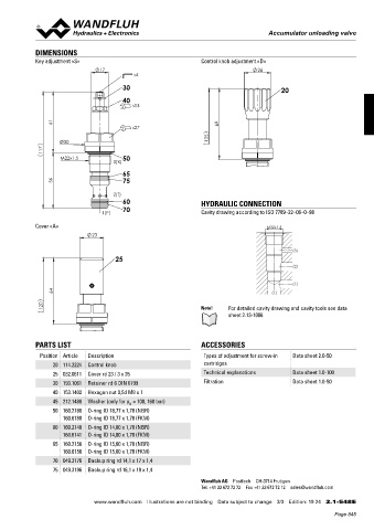
Accumulator unloading valve
DIMENSIONS
Key adjustment «S» Control knob adjustment «D»
17 26
s4
30 20
40
s13
61 69
s27
125
Ø30
117
M22x1.5 50
3(X)
65
56 75
2(T)
60 HYDRAULIC CONNECTION
70
1(P) Cavity drawing according to ISO 7789–22–06–0–98
Cover «A» M22x1.5
23
(3)
25
(2)
(1)
64 (1)
120 Note! For detailed cavity drawing and cavity tools see data
sheet 2.13-1006
PARTS LIST ACCESSORIES
Position Article Description Types of adjustment for screw-in Data sheet 2.0-50
20 114.2224 Control knob cartridges
25 032.0611 Cover rd 23 / 3 x 35 Technical explanations Data sheet 1.0-100
30 193.1061 Retainer rd 6 DIN 6799 Filtration Data sheet 1.0-50
40 153.1402 Hexagon nut 0,5d M8 x 1
45 212.1488 Washer (only for p = 100, 160 bar)
N
50 160.2188 O-ring ID 18,77 x 1,78 (NBR)
160.6188 O-ring ID 18,77 x 1,78 (FKM)
60 160.2140 O-ring ID 14,00 x 1,78 (NBR)
160.6141 O-ring ID 14,00 x 1,78 (FKM)
65 160.2156 O-ring ID 15,60 x 1,78 (NBR)
160.6156 O-ring ID 15,60 x 1,78 (FKM)
70 049.3176 Backup ring rd 14,1 x 17 x 1,4
75 049.3196 Backup ring rd 16,1 x 19 x 1,4
Wandfluh AG Postfach CH-3714 Frutigen
Tel. +41 33 672 72 72 Fax +41 33 672 72 12 sales@wandfluh.com
www.wandfluh.com Illustrations are not binding Data subject to change 3/3 Edition: 19 24 2.1-548 E
Page 845