
Page 840 - Softbound_Edition_19_en
P. 840
Pressure relief valve
Pressure relief valves Pressure sequence valves
Pressure sequence valve
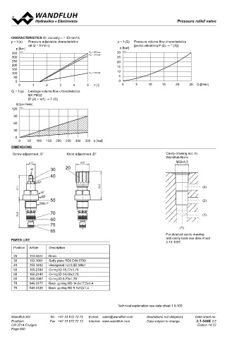
chaRacteRistics Oil viscosity υ = 30 mm /s
2
p = f (n) Pressure adjustable characteristics p = f (Q) Pressure volume flow characteristics screw-in cartridge
(at Q = 5 l/min) [pump unloading P (2) → T (3)] • Pilot operated M22x1,5
p [bar] p [bar] • Q = 100 l/min
350 K0373 P N = 350 bar 30 K0374 • p max = 400 bar ISO 7789
P N = 315 bar
300 25 max
250 20 • p n max = 350 bar
200 15
150 10 DescRiPtion Function aPPlication
100 P N = 100 bar Pilot operated pressure sequence valve in The pressure sequence valve connects con- For sequence control of operating sequences,
50 5 screw cartridge construction with M22x1,5 sumers in hydraulic circuits. Its separate whereby a consumer is switched on when a
0 0 thread for cavity acc. to ISO 7789. The valve leakage line means that the valve can be used specific pressure is reached. Operates as a
0 1 2 3 4 5 n [-] 0 5 10 15 20 25 Q [l/min] is available with 2 different types of adjustment: as a pressure relief valve that is not sensitive to pressure relief valve for controls where ram
key ad-justment „S“ and control knob adjust- ram pressure. When the set pressure has been pressure in the secondary line may not affect
Q = f (p) Leakage volume flow characteristics ment „D“ both of which are fixed, and a lockable reached, the pilot operation opens to the tank, the pressure setting. The screw cartridges are
L
BX.PM22 version „K“. Key adjustment „S“ is also avai- thereby opening the main spool to the next very well suited for use in control blocks and are
[P (2) + x(1) → T (3)]
lable with cover see data sheet 2.0-50. Three consumer. Pilot operated pressure sequence installed as functional parts in the Wandfluh-
Q [cm /min] pressure ranges are available as standard: 63, valves can be very finely adjusted and are Hydraulik NG4, NG6 and NG10 sandwich
3
120 K1180 160 and 350 bar. The steel cartridge body is suitable for high volume flows and pressures. plates (vertical stacking). Please see separate
zinc coated and thus protected against rust. There is very little play in the hardened spool, data sheets in register 2.1). Step tools are avai-
90 thus leakage is kept to a minimum. lable (for hire or purchase) for the manufacture
of the cartridge cavities in steel or aluminium
60 blocks. See data sheets in register 2.13
P(2) P(2)
30
0 x(1) x(1) tYPe coDe
0 50 100 150 200 250 300 350 p [bar] F V PM22 - #
Pressure sequence valve
DiMensions T(3)
T(3)
Screw adjustment „S“ Knob adjustment „D“ Cavity drawing acc. to Pilot operated
Wandfluh-Norm Type of adjustment Key S
Ø 17 ø 26 M22x1,5 Control knob D
s4 30 20 Cover A (see data sheet 2.0-50)
40 Screw cartridge M22x1,5
s13 Pressure range p N 63 bar 63
47,1 54,6 (3) 160 bar 160
s27 350 bar 350
ø30
50 (2) Design-Index (Subject to change)
M22x1,5
53,5 70 (1) GeneRal chaRacteRistics hYDRaulic chaRacteRistics
60 Description Pilot operated pressure sequence valve Hydraulic fluid Mineral oil, other media on request
75 (1) Construction Screw cartridge for cavity acc. to ISO 7789 Max. permissible ISO 4406:1999, class 18/16/13
M22x1,5 screw thread
Type of fixture
contamination level
(recommended filter gauge ß 6…10≥75)
65 Ambient temperature -20…+50°C see also data sheet 1.0-50/2
For detailed cavity drawing Installation position any Viscosity range 12 mm /s…320 mm /s
2
2
PaRts list and cavity tools see data sheet Tightening torque M = 50 Nm Hydraulic fluid temp. -20…+70°C
D
2.13-1037. Weight m = 0,17 kg (key) Peak pressure p max = 400 bar
Position Article Description m = 0,18 kg (control knob) p Tmax = p +20 bar
P
Rated pressure ranges p = 63 bar, p = 160 bar, p = 350 bar
N
N
N
Minimum pressure see curve
20 114.2224 Knob Volume flow Q = 0,2…100 l/min
30 193.1061 Safty plate RD6 DIN 6799 Leak volume flow see curve
40 153.1402 Hexagonal nut 0,5D M8x1 Control volume flow Q = 0,1…0,4 l/min (dep. on pressure)
St
50 160.2188 O-ring ID 18,77x1,78
60 160.2140 O-ring ID 14,00x1,78 sYMBol Mechanical actuation
65 160.2087 O-ring ID 8,73x1,78 Mechanical types of operation in 2 different versions:
70 049.3177 Back up ring RD 14,6x17,5x1,4 S = Screw adjustment
with fork wrench and Allen key
75 049.3126 Back up ring RD 9,1x12x1,4 P(1) D = Control knob adjustment, fixed
Actuation stroke S = 5 mm
b
Actuation angle α = 1800° (5 turns)
b
Technical explanation see data sheet 1.0-100 x(3) A(2)
Wandfluh AG Tel. +41 33 672 72 72 E-mail: sales@wandfluh.com Illustrations not obligatory Data sheet no. Wandfluh AG Tel. +41 33 672 72 72 E-mail: sales@wandfluh.com Illustrations not obligatory Data sheet no.
Postfach Fax +41 33 672 72 12 Internet: www.wandfluh.com Data subject to change 2.1-544E 2/2 Postfach Fax +41 33 672 72 12 Internet: www.wandfluh.com Data subject to change 2.1-546E 1/2
ø
26
17
CH-3714 Frutigen Edition 14 22 CH-3714 Frutigen Edition 10 33
Ø
Page 840 s4 30 20
40
s13 48,1
40,6
s27
ø30 50
M22x1,5
65
54 75
60
70