
Page 825 - Softbound_Edition_19_en
P. 825
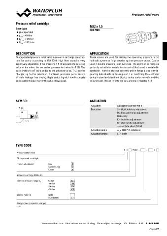
Pressure relief valve
 Pressure relief valves                                                                        Pressure relief valve


            Pressure relief cartridge
 CHARACTERISTICS Oil viscosity υ = 30 mm /s
 2
 p = f (Q)    Pressure volume flow characteristics   p = f (Q)   Pressure volume flow characteristics  Seat tight  M22 x 1,5
    (Maximal adjustable pressure)      (Minimal adjustable pressure)  ISO 7789
 p [bar]  p [bar]  ◆  pilot operated
 400  K0675  P N = 350 bar  20  K0676  ◆  p  = 450 bar
                max
             ◆  p N max  = 420 bar
 300  15
             ◆  Q  = 100 l/min
                max
 200  10
 P N = 160 bar
 100  P N = 63 bar  5
            DESCRIPTION                                          APPLICATION
 0  0       Pilot operated pressure relief valve in screw-in cartridge construc-  These  valves are  used  for  limiting the operating  pressure  in  the
 0  20  40  60  80  Q [l/min]  0  20  40  60  80  Q [l/min]
 p = f (n)   Pressure adjustment characteristics  ∆p = f (Q)  Pressure volume flow characteristics  tion  for  cavity  according  to  ISO  7789.  High  flow  capacity,  very    hydraulic system or for protection against pressure peaks.  Can be

            (at Q = 5 l/min)     [control line  x unpressurised circ. - bypass P (1) → T (2)]  sensitively adjustable. If the pressure in P (1) exceeds the adjusted   used in double pressure relief switches. The screw-in cartridge is
 p [bar]  p [bar]  value of the valve, the excessive pressure is drained to T (2). The   perfectly suitable for installation in control blocks and is installed in
 400  K0113  20  K0677  back pressure at T (2) is added to the adjusted value. T (2) can be   sandwich-  (vertical stacked systems) and in flange plates (corres-
 P N  = 350 bar
 300  15    charged  up  to  the  maximum.  Hardened  precision  parts  ensure   ponding data sheets in this register). For machining the cartridge
            virtually leakage-free closing. Rapid switching with low hysteresis   cavity in steel and aluminum blocks, cavity tools are available (hire
 200  10    and excellent stability over the whole flow range.    or purchase). Please refer to the data sheets in register 2.13.
 P (1)  P N  = 160 bar
 100  P (1)  P N  = 63 bar  5
 x (3) 0  0
 0  1  x (3) 2  3  4  5  n [-]  0  20  40  60  80  Q [l/min]
 T (2)
 DIMENSIONS
    Screw adjustment «S»   T (2)  Knob adjustment  «D»   SYMBOL      ACTUATION
                                                                  Actuation          Adjustment spindle M8 x 1
 ø 26  Cavity drawing to   T (2)
 Ø  17  ø 26  M22 x 1,5  ISO 7789–22–07–0–98                      Execution          S = blockable key adjustment
 s4  30  Ø 17 20  20  M22 x 1,5                                                      D = blockable knob adjustment
 40  s4  30                                                                          Optionally:
 40                                                                                  K = lockable adjustment
 s13               P (1)                                                             G = star handle adjustment
 47,1  s13  54,6  (3) X                                                              → see Data sheet 2.0-50
 s27  47,1  54,6  (3) X                                           Actuation angle    a  = 1800 ° (5 rotations)
                                                                                      b
 ø30  s27  (2) T                                                  Actuation stroke   S  = 5 mm
 50  ø30                                                                              b
 M22x1,5  50  (2) T
 60  M22x1,5
 x(3)  60  (1) P
 54  54 70  x(3)  (1) P  TYPE CODE
 T(2)  70                                                                                B  C     PM22  -     -     #
 65  T(2)  (1) P  Pressure relief valve

 P(1)  75  65  (1) P  Pilot operated, seat tight
 P(1)  75  For detailed cavity drawing and cavity
 tools see data sheet 2.13-1007.  Type of adjustment   Key   S
                                    Control knob    D
                                    Cover           A

             Screw-in cartridge M22 x 1,5
 PARTS LIST
             Nominal pressure range p N   63 bar    63
   Position   Article           Discription     160 bar   160
                                    350 bar         350
 20   114.2224   Knob               420 bar         420
 30   193.1061   Safty plate RD6 DIN 6799
 40   153.1402   Hexagon nut 0,5D M8x1  Sealing material   NBR  D1
                                    FKM (Viton)

 50   160.2188   O-ring ID 18,77x1,78
 60   160.2156   O-ring ID 15,60 x 1,78  Design index (subject to change)
 65   160.2120   O-ring ID 12,42 x 1,78  2.1-538
 70   049.3196   Back-up ring RD 16,1 x 19 x 1,4
 75   049.3157   Back-up ring RD 12,6 x 15,5 x 1,4  Technical explanation see data sheet 1.0-100


 Wandfluh AG   Tel.  +41 33 672 72 72   E-mail:  sales@wandfluh.com   Illustrations not obligatory   Data sheet no.
 Postfach   Fax  +41 33 672 72 12   Internet:  www.wandfluh.com   Data subject to change   2.1-534E 2/2  www.wandfluh.com  Illustrations are not binding  Data subject to change  1/3  Edition: 18 41  2.1-538 E
 CH-3714 Frutigen                   Edition 10 33
                                                                                                            Page 825